Introduction
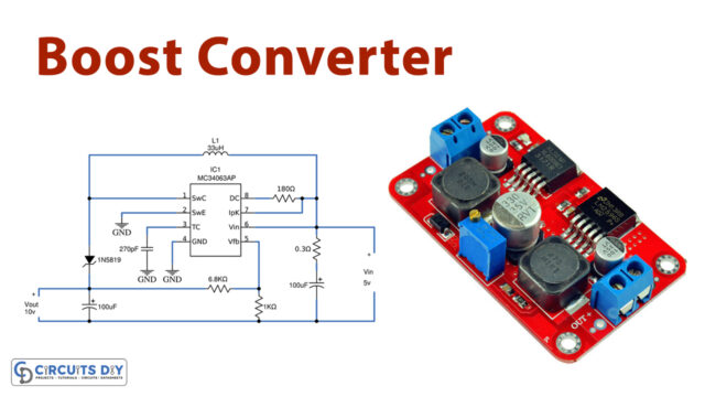
Sometimes while making the circuits, we get into the troublesome situation where we want some more supply than the power supply available. For example, we only have 3V DC available but we need 9V or 12 V DC. At this time, the circuit known as the “boost converter” gets utilized. It helps to boost up the input DC voltage and provide it at the output side so that it may get used by the other device that needed the greater voltage. Conversion from lower to higher voltage is not that much difficult as we have already learned about the AC to DC converter. But, this circuit is about DC to DC conversion. Hence, in this tutorial, we are going to “Boost Converter Circuit Using MC34063 IC”
Hardware Required
| S.no | Component | Value | Qty |
|---|---|---|---|
| 1. | IC | MC34063AP | 1 |
| 2. | Schottky Diode | 1N5819 | 1 |
| 3. | Inductor | 33µH | 1 |
| 4. | Capacitors | 100µF, 270pF | 2, 1 |
| 5. | Resistor | 0.3Ω, 1KΩ, 6.8KΩ, 180Ω | 1, 1, 1, 1 |
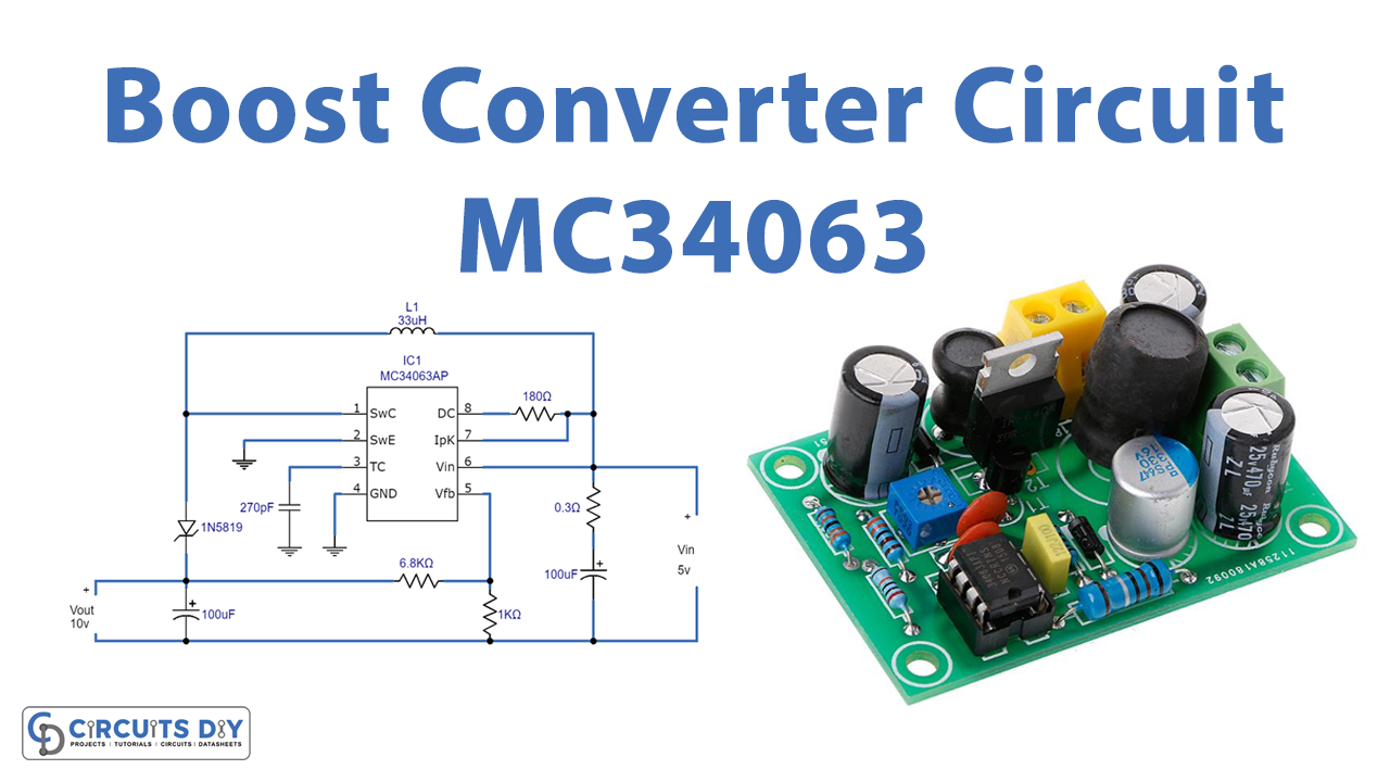
Circuit Diagram

Working Explanation
In this Boost Converter Circuit Using MC34063 IC is used as a DC-DC Boost converter which will provide an output of 10V by taking the 5V input from the supply at Vin pin 6. . After connecting all elements in the circuit take the output reading at capacitor C1. Also determine the output voltage by applying the following formula: V out= 1.25( 1+R2/R1). Now compare both. You may see that practical output voltage may be varied because of the inductor value.
Application and Uses
- photovoltaic cells can use these boost converter circuits.
- In battery power supplies, etc.
- Different electronic devices use this circuit.
- Telecommunication devices.
- Consumer electronic devices.