Introduction
Hearing is no doubt a great blessing. It’s something that we all should be thankful to our lord. However, we also must have to count and take care of those who can’t hear. And, now we live in that modern era where hearing aid devices are readily available. But, have you ever thought of making that device by yourself to explore how it works? If not, then we are here in this Tutorial we are going to make a “Cheap & Small hearing aids circuit project”
In the making of the circuit, we are using two NPN transistors. BC547 and BC337. So, let’s first take a look at their features.
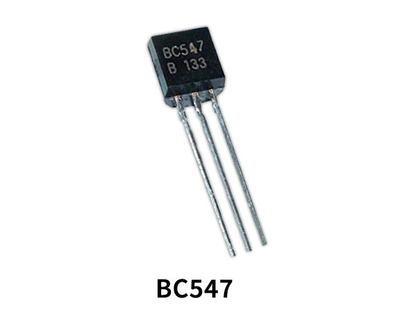
BC547 Transistor Features
- Transistor Type: NPN
- Max Collector Current(IC): 100mA
- Max Collector-Emitter Voltage (VCE): 45V
- Max Collector-Base Voltage (VCB): 50V
- Max Emitter-Base Voltage (VEBO): 6V
- Max Collector Dissipation (Pc): 500 miliWatt
- Max Transition Frequency (fT): 300 MHz
BC337 Transistor Features
- Continuous Collector Current(IC): 800 mA
- Collector-Emitter Voltage (VCE): 45 V
- Collector-Base Voltage (VCB): 50 V
- Emitter-Base Voltage (VBE): 5 V
- Collector Dissipation (Pc): 625 W
- Transition Frequency (fT): 100 MHz
- DC Current Gain (hFE): 100 – 630
Hardware Required
| S.no | Component | Value | QTy |
|---|---|---|---|
| 1. | Transistor | BC547 & BC337 | 3, 1 |
| 2. | Resistor | 10K, 1M, 4.7K, 100K, 3.9K, 1.5K, 100 Ohm | 2, 1, 1, 2, 1, 1, 1 |
| 3. | Capacitor | 0.1uF, 10uF, 1uf, 470pF, 470uF | 2, 1, 2, 1, 1 |
| 4. | Switch(Single Pore Double Switch) | – | 1 |
| 5. | Mic & Battery | – | 1, 1 |
| 6. | Variable Resistor | 50K | 1 |
| 7. | Diode | 1N4148 | 1 |
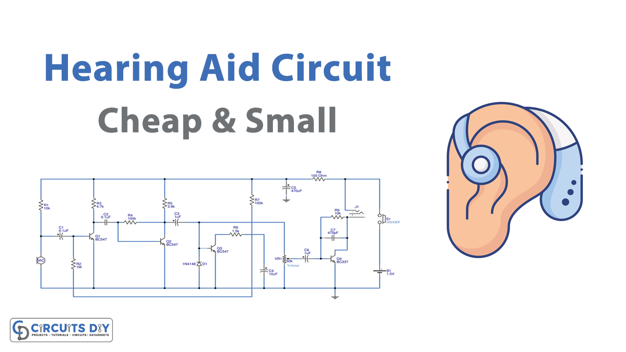
Circuit Diagram
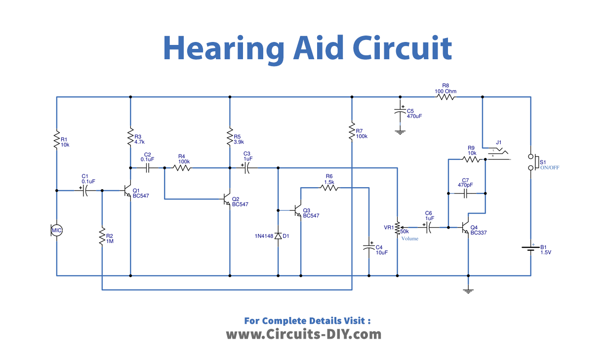
Working Explanation
In this Cheap & Small hearing Aids Circuit Project, firstly, a condenser microphone is there. However, this MIC needs a source of DC voltage. Therefore, it receives DC from a battery through resistor R1 (10K).
Pre Amplifier Circuit
Now, the 0.1uF C1 capacitor receives an audio signal from the MIC. This capacitor passes the AC signal to the transistor Q1 which amplifies the coming signal. This completes the first audio amplifier set. Now, the output signal coming from capacitor C2 is coupled to transistor Q2 at the collector. It serves as a backup preamplifier. This is a substantial gain. Resistors R3 and R5 are working as a load, while resistor R4, is a feedback resistor.
Automated level Control Circuit
It has a transistor-Q3 for automated level control. To regulate the amplifier’s volume, it creates a feedback bias current at the base of Q1. A diode is there to rectify voltage.
A volume control step is delayed by capacitor C4. Smaller values speed up the sound’s rhythmic up-and-down control. However, if the value is big, the sound control will be slower.
It then sends a signal through R2 to the base of Q1. If MIC1 has a loud voice. The collector voltage of transistor Q3 will be lower, resulting in a lower voltage for capacitor C4.
This control voltage will now enter the transistor Q1’s base through resistor R2. A bias current to the Q1 will operate more vigorously and produce a louder sound if the voltage is high. However, If the level volume control voltage is low, the transistor’s current input would drop as a result. The audio stream will therefore be lowered As a result, the sound level is almost constant. whatever the volume.
The signal then passes via a circuit of a power amplifier to drive headphones for hearing.
Power Amplifier
A sound signal is amplified using transistor Q4-BC37. The loudness is adjusted using a potentiometer VR1. Capacitor C9 Connect signals to the transistor Q4’s base. Additionally, a signal and bias are sent back to the class A transistor through the R9 resistor. By using capacitor C7, it lowers the gain in the high-frequency band.T to keep the circuit stable while reducing noise, Headphones are directly linked to the power supply and get the audio signal from the collector.
Thus, the headphone is a load of this circuit
Application Uses
- Hearing aid devices.