Introduction
Are you researching some circuits that can increase the efficiency and flexibility of industrial machines? Building a 3-phase variable-frequency drive (VFD) circuit can help you achieve this goal. Not only does a VFD circuit allow for precise control of a motor’s speed, but it also reduces energy consumption and extends the life of the motor. This article will guide you through building your 3-phase VFD circuit, from selecting the right components to wiring and programming the circuit.
Whether you’re a professional electrician or a DIY enthusiast, this guide will provide all the information you need to get started on your VFD circuit project. So, come along, let’s dive into the world of VFD and learn the art of building the perfect 3-phase VFD Circuit.
What is VFD, and where is it Employed?
A variable frequency drive (VFD) is a motor controller that changes the voltage and frequency of the electricity flowing through an electric motor. A variable frequency drive controls the motor’s torque, speed, and direction to give it a smooth start and a controlled rate of acceleration.
A variable frequency drive (VFD) is employed to run either an alternating current (AC) induction motor or a synchronous motor.
Components Required
The major components that you need for the circuits are:
| S.no | Component | Value | Quantity |
|---|---|---|---|
| 1 | IC | 555 timer | 2 |
| 2 | transistor | BC557 | 1 |
| 3 | IC | IRS2330 | 1 |
| 4 | IC | CD4035 | 1 |
| 5 | IC | CD4009 | 1 |
| 6 | IC | 4060 | 1 |
| 7 | LED/LDR assembly | – | 1 |
| 8 | IGBTs or MOSFETS | – | 3 |
| 9 | preset (RMS control knob) | 1K | 1 |
| 10 | frequency-dependent resistor | 1M | 1 |
| 11 | 3-phase signal generator | – | 1 |
| 12 | Power supply | – | 1 |
It’s important to note that these are just a summary of the components required, and you should refer to the circuit diagrams and connections for more detailed hardware requirements.
Steps to Build a 3-Phase VFD Circuit
Follow the given circuit diagrams and connection table to make a 3-phase VFD circuit.
Circuit Diagram


Connections
Here are the connections for each circuit in bullet points:
PWM Voltage Controller Circuit:
- IC1 output is connected to the IC2 trigger pin
- IC2 chip is connected to a 1K preset RMS control knob
- PWM output is produced across pin3 of IC2 in response to the voltage applied at pin5
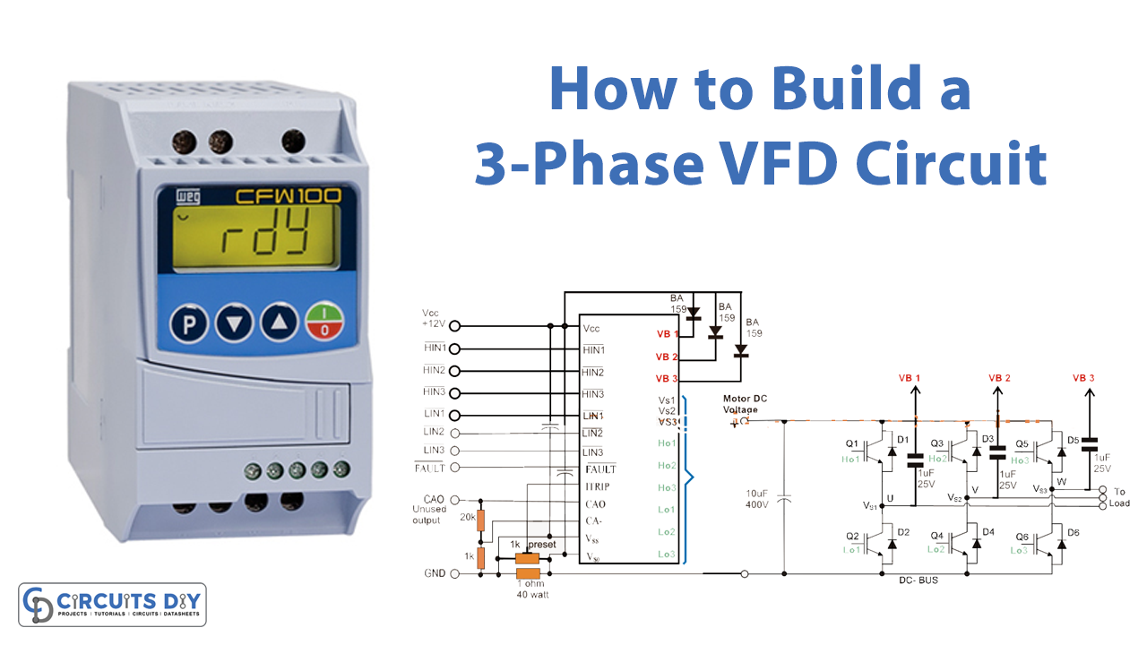
3 Phase High Side/Low Side H-Bridge Driver Circuit:
- IC IRS2330 is used as the single-chip H-bridge driver.
- The inputs are also connected to the PWM output from the previous stage for voltage regulation
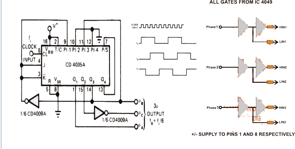
3-Phase Generator Circuit:
- The circuit is designed using CMOS chips CD4035 and CD4009
- Produces precisely dimensioned 3-phase signals across the demonstrated pinouts
- The frequency of the signals is based on input clocks, which must be six times the intended 3-phase signal
Voltage to Frequency Converter Circuit:
- IC 4060 is used for the conversion.
- Frequency-dependent resistance is affected by an LED/LDR assembly.
- LDR has located across a 1M frequency-dependent resistor of the IC
- LED illumination varies in response to PWMs from the first PWM circuit stage, resulting in a correspondingly varying frequency at pin3 of IC 4060
It’s important to note that these are just a summary of the connections, and you should study the whole circuit diagram to fully understand each circuit’s connections and functionality.
Working Explanation
The 3 phase variable frequency drive (VFD) circuit is made up of several essential components, including:
- A PWM voltage controller circuit
- 3-phase high side/low side H-bridge driver circuit
- 3-phase generator circuit
- Voltage-to-frequency converter circuit for producing the V/Hz parameter.
A PWM voltage controller circuit
The circuit’s first stage, the PWM voltage controller circuit, uses an IC2 chip to produce a PWM output across pin3 in response to the voltage applied at pin5. The 1K preset in the diagram is the RMS control knob, which you can adjust to obtain the desired proportion of output voltage through PWMs at pin3 of IC2 for further operation.
3-phase high side/low side H-bridge driver circuit
The next stage is a single-chip H-bridge 3-phase driver circuit using the IC IRS2330. The design is simple, as the chip’s built-in advanced circuitry handles many difficulties. A properly determined 3-phase signal is used across the HIN1/2/3 and LIN1/2/3 inputs of the IC through a 3-phase signal generator stage. These inputs of the IC can also be observed built-in with the above PWM output for the essential voltage regulation across the IGBTs or MOSFETS associated with the 3-phase motor.
3-phase generator circuit
The 3-phase generator circuit is designed around several CMOS chips, CD4035 and CD4009, which produce precisely dimensioned 3-phase signals across the demonstrated pinouts. The frequency of the 3-phase signals varies according to the input clocks, which must be six times the intended 3-phase signal.
Voltage-to-frequency converter
A voltage-to-frequency converter circuit using an IC 4060 is essential for automatic frequency modification in response to different voltages. The circuit uses an LED/LDR assembly for the intended conversions, with the LDR located across a 1M frequency-dependent resistor of the IC. As the LED illumination varies, the LDR produces a correspondingly varying (increasing or decreasing) frequency across pin3 of the IC 4060.
Finally, this differing frequency from the IC 4060 is integrated with the 3-phase signal generator circuit to control the frequency of the motor.
Final Words
In conclusion, building a 3-Phase VFD circuit can be a challenging task. Still, it is possible to make a driver circuit that works well with the right knowledge and components. If you have any queries or comments, please feel free to reach out. Thank you for reading!