Introduction
Are you interested in creating your contact microphone circuit for audio recording or experimentation? A contact microphone, also known as a piezo microphone, is a device that captures vibrations from physical surfaces and converts them into electrical signals. Building your own DIY contact mic circuit is an excellent way to learn about essential electronic components and gain experience in circuit building.
This blog will guide you through building a simple yet effective contact microphone circuit using easy-to-find components. We will cover the necessary components, circuit diagram, and step-by-step instructions to help you create your own contact mic. Whether you’re a beginner or an experienced electronics enthusiast, this blog will provide the knowledge and skills you need to make your DIY contact mic circuit.
Hardware Required
| S no | Components | Value | Qty |
|---|---|---|---|
| 1 | MOSFET | MPF102 | 1 |
| 2 | Capacitor | 4.7, 10uF | 3 |
| 3 | Resistor | 1.5k, 3.3M, 560, 220k | 1, 1, 1, 1 |
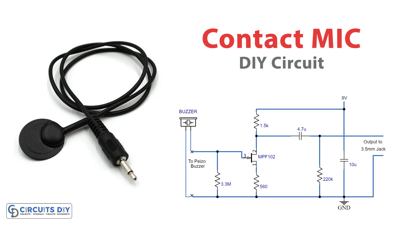
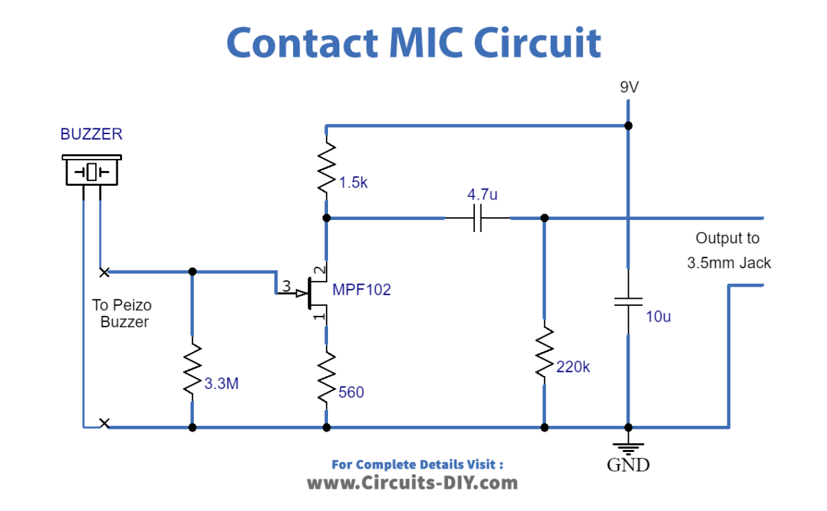
Circuit Diagram
Working Explanation
This circuit is an amplifier that takes an input signal and makes it stronger. The circuit uses a battery that provides 9 volts, which is connected to a device called a JFET, specifically the MPF-102. One end of the amplifier is connected to both the input and output signals, which is called the JFET drain terminal. This circuit is also known as a “common drain circuit.” The other end of the circuit, called the JFET source terminal, is connected to the battery’s ground terminal through a resistor with a value of 1.5k.
The main component used in this circuit is the MPF-102 transistor. When there is no signal, a bias voltage causes a very small current to flow through the JFET source terminal. This sets the source voltage at a point halfway between the supply and ground. This is the recommended bias setting for most small-signal or analog audio amplifiers, as it allows the maximum signal before distortion.
The input signal enters the amplifier through a resistor with a value of 3.3M. This resistor drops the voltage of the AC input signal to the JFET gate. The JFET amplifies the signal by varying the current flow through it. The difference between the source and the gate sets the voltage drop across a resistor with a value of 560 Ω. Typically, the bias voltage across this resistor carries the JFET channel at a medium resistance value. When an input signal is applied, the voltage across this resistor changes, causing the JFET to vary the current flow through it. This leads to the amplification of the input signal.
The output signal appears between the JFET source terminal and the ground. A capacitor with a value of 4.7uF blocks DC voltages in the circuit but allows the amplified AC signal to pass through. Since the JFET gate is more negative than the ground terminal, the output signal appears across the JFET source terminal and ground. However, since the source terminal is connected to the supply voltage, the source terminal is more positive than the ground terminal. This causes the output signal to leave the amplifier through the capacitor and appear across a resistor with a value of 220k. This capacitor only allows AC signals to pass through and blocks DC signals.
Conclusion
We hope you found this guide helpful in building your own DIY contact microphone circuit. By following the instructions and using the recommended components, you can create a high-quality contact mic that will provide you with reliable and accurate sound recording capabilities. As you gain experience with circuit building, you can experiment with different components and configurations to customize your contact mic to meet your specific needs.
Don’t hesitate to reach out if you have any questions or need further assistance. We love hearing from our readers and are always here to help. Thanks for reading, and happy circuit building!