IR or infrared radiations are electromagnetic radiation having wavelengths longer than those of other visible lights. Even though our eyes are very sensitive to light but we can not see IR radiations. Therefore it is not possible for us to test or check whether the equipment emitting IR radiations are working or not.
In this tutorial, we are going to make an IR Detector Circuit it will detect IR from any equipment. This circuit is using only six components it is cheap and can easily be made in a few steps. The main component is a phototransistor L14G2. It converts the light energy into electrical energy by capturing it and exposing it to the photodiode enclosed inside the package. This sensor has a small lens on the top for focusing the maximum amount of light on the photodiode. This photosensor/transistor is commonly used in applications of color, light, or dark sensing, proximity detection, etc.
Hardware Components
The following components are required to make IR Detector Circuit
| S.no | Component | Value | Qty |
|---|---|---|---|
| 1. | Battery | 9V | 1 |
| 2. | Resistors | 22K, 15K, 470Ω | 1,1,1 |
| 3. | LED | 5mm | 1 |
| 4. | Transistor | L14G2 | 1 |
| 5. | Transistor | 2N3905 | 1 |
| 6. | Breadboard | – | 1 |
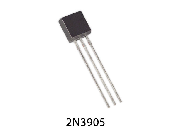
2N3905 Pinout
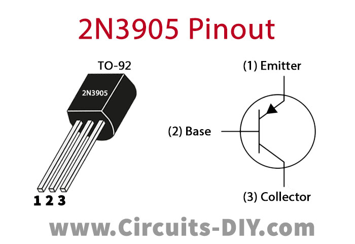
For a detailed description of pinout, dimension features, and specifications download the datasheet of 2N3905
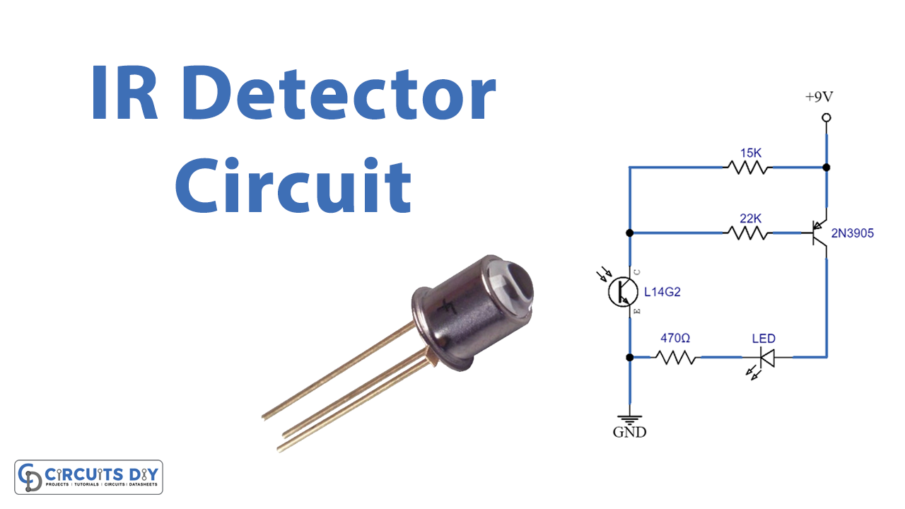
IR Detector Circuit
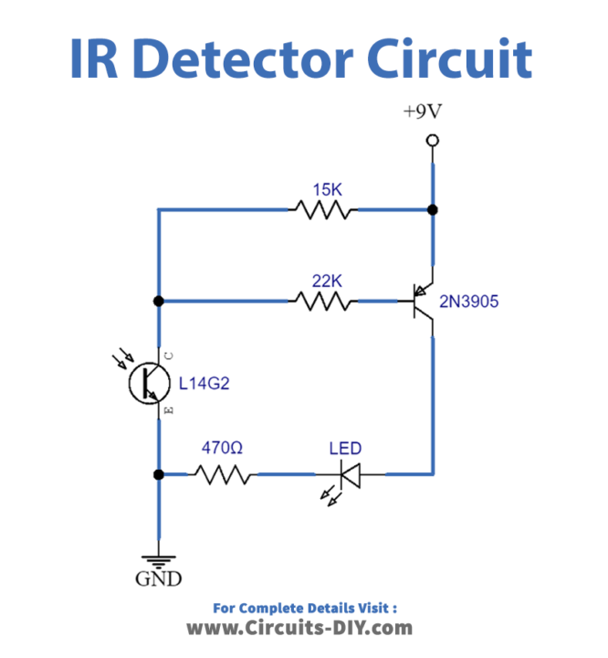
Working Explanation
The operating voltage of this circuit is 9 volts. On receiving power the circuit will remain off until the phototransistor T1 senses the infrared beam and converts it into electrical energy. This will power up the transistor T2.
T2 is working as an amplifier in this circuit. It will amplify the output of transistor T1 and turns the LED on. LED is used to provide a visual indication of the proper working of the equipment being tested.
Applications and Uses
- Proximity Detection
- Light detection
- Automatic lighting applications
- Color detection