Introduction
In this tutorial, we are going to make the “LM1036-LM1035 Dual DC Tone Control Circuit”. For stereo applications in automobile radio, television, and audio systems, the LM1035/LM1036 is a DC-controlled tone and balancing circuit IC. The IC has four control inputs that allow four potentiometers to regulate the volume, balance, treble, and bass.
To make this circuit we are using PCB Board. So, you shouldn’t fear if you are just a newbie. If something initially doesn’t work out well, it’s okay, it eventually will be.
Since In making the circuit, we are using LM1306/ LM1305 Dual DC control volume balanced integrated circuits. Therefore, before going forward, let’s briefly discuss their features
LM1036-LM1035 Features
- Wide supply voltage range, 8V to 18V
- Extensive volume control range: 75 dB typical
- Tone control: ±15 dB typical
- Channel separation: 75 dB typical
- Low distortion: 0.06% typical for an input level of
- Vrms: 0.3 (for LM1036)
- Signal-to-noise ratio: High, 80 dB typical for an input level of
Pin Configuration of LM1036-LM1035
| Pin Number | Description |
| 1 | Internal Supply decouple |
| 2 | Input (Here we have attached the preamplifier circuit) |
| 3 | Treble Capacitor 1 |
| 4 | For Treble control Input |
| 5 | AC bypass 1 |
| 6 | Bass Capacitor 1 |
| 7 | Loudness compensation control input 1 |
| 8 | Output 1 |
| 9 | Balance control input |
| 10 | Ground |
| 11 | Vcc |
| 12 | Volume control input |
| 13 | Output 2 |
| 14 | Bass control input |
| 15 | Bass capacitor 2 |
| 16 | AC Bypass 2 |
| 17 | Zener Voltage |
| 18 | Treble Capacitor 2 |
| 19 | Input 2 ( Here we connect the preamplifier circuit) |
| 20 | Ground |
Hardware Required
| Sr No: | Components | Value | Qty |
|---|---|---|---|
| 1 | Transistor | – | 2 |
| 2 | Variable Resistor | 850K | 4 |
| 3 | Resistor | (Different Values) | 23 |
| 4 | Capacitor | (Different Values) | 19 |
| 5 | IC | LM1035 , LM1036 | 1 |
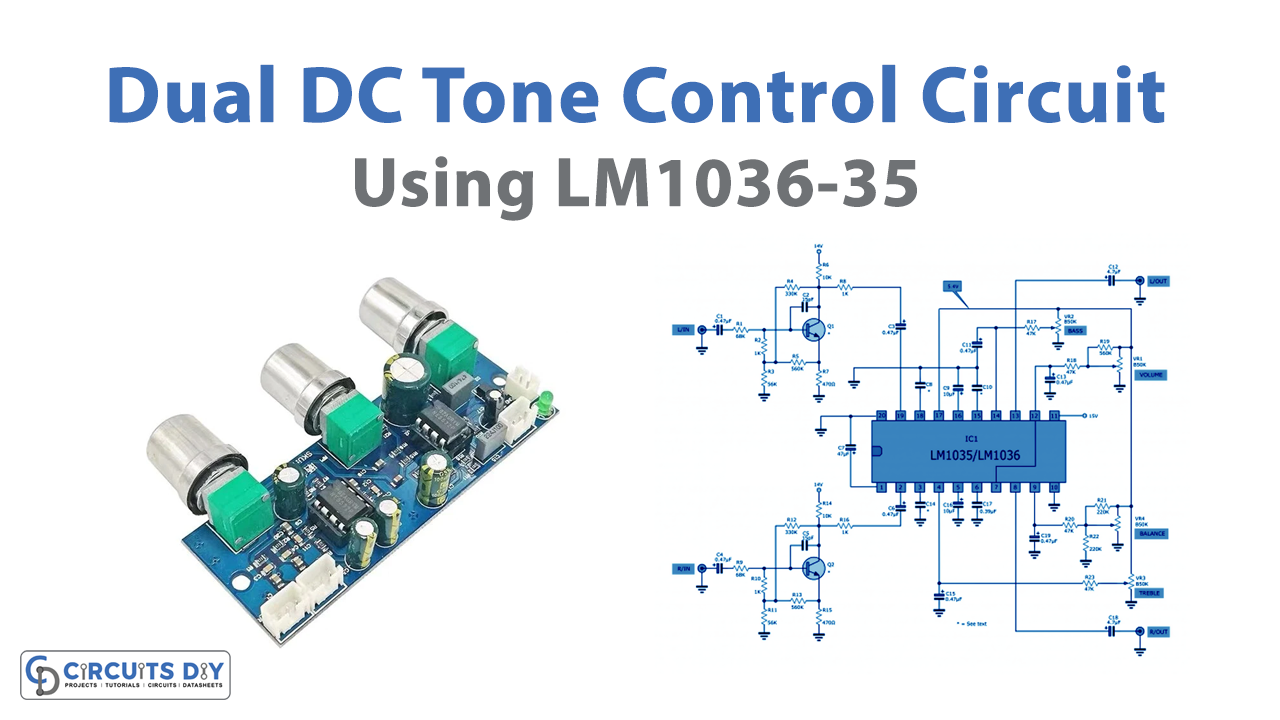
Circuit Diagram

Working Explanation
This LM1036-LM1035 Dual DC tone control circuit with PCB uses different external components to work significantly. The power supply voltage is connected to IC1 pin 11. The voltage range for this IC is 8V to 18V. The circuit includes two preamplifier circuits connected to pin 19 and pin 2.
To decrease transient at the bot pins, there are capacitors C2 and C5. Additionally, there are two resistors for the bias and divider: R2-R7 for pin 19 and R9-R15 for pin 2. They serve as Q1’s and Q2’s respective bias working points. The signal then exits via pin C after passing through R8 and R16. Now, connect these preamplifier circuits to input pins 19 and 2 of the IC through C3 and 6.
Now, there are four potentiometers for tone control. VR2 and VR3 can produce boots and reduce bass and treble noises. While VR1 controls the volume. VR4 is there for adjusting the balance. The balance part is the most crucial; if only one volume is used, the balancing will not be accurate. because the potentiometer’s value is not truly linear. Therefore, to create a proper balance, we employ R21 and R22.
Pins 13 and 8 on this circuit will produce the circuit’s output signal. The circuit output is then coupled through C2 and C18.
Application Uses
- In different audio systems
- For car radios.
- Televisions.