The audio level meter is a circuit that detects and measure the level of audio/sound in the surrounding. These sound circuit converts sound energy from the surrounding into electrical energy to light LEDs accordingly. A number of transistors, LEDs, and an electret mic make up the sound/ audio level meter.
Hardware Components
The following components are required to make Audio Level Meter Circuit
| S.no | Component | Value | Qty |
|---|---|---|---|
| 1. | Transistor | 2N4401, 2N3904 | 3, 15 |
| 2. | LEDs | 25mA | 36 |
| 3. | Electret Microphone | – | 1 |
| 4. | Resistors | 10k, 620k, 220k, 1.2k, 5.1k, 75ohm | 2 |
| 5. | Variable Resistor | 100k | 1 |
| 6. | Ceramic Capacitor | 100nF | 2 |
| 7. | Diodes | 1N4148 | 15 |
| 8. | Power Supply | 12v | 1 |
| 9. | Electrolytic Capacitor | 10uF | 2 |
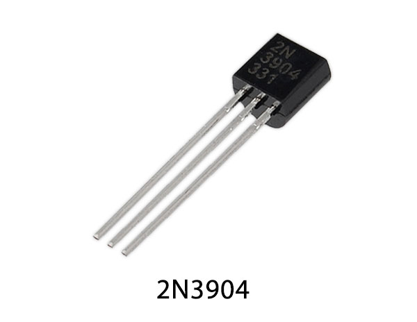
2N3904 Pinout
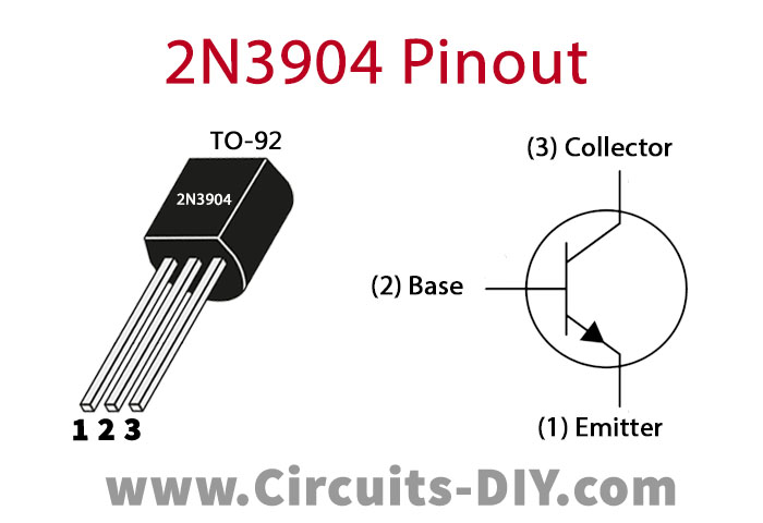
For a detailed description of pinout, dimension features, and specifications download the datasheet of 2N3904
Audio Level Meter Circuit
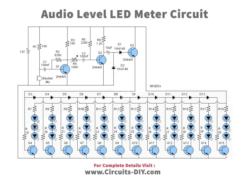
Working Explanation
Here, the project consists of 36 LEDs, 15 transistors, and a combination of resistor and capacitor. The main part of the circuit is the transistors Q1, Q2, and Q3 that are accountable for sound detection and amplification. Electret microphone catches the sound from the surroundings and converts it into an electrical signal. This electrical audio signal is then amplified by the transistors Q1 and Q2. Moreover, the sensitivity of the overall circuit is adjusted through the 100KΩ potentiometer. Furthermore, the sensitivity can also be decreased by replacing the variable resistor of 100KΩ with 200KΩ or 300KΩ.
Now, this amplified signal goes through the filtering and rectification part. After the 10µF electrolytic capacitor filters the amplified electrical signal, diodes D1, and D2 rectify it into a DC signal. This DC signal enters the base of transistor Q3 and thus, activates it.
The third part of the circuit consisting of transistors Q4 to Q15 connected with LED depends entirely upon the ON/OFF signal from transistor Q3. Once, transistor Q3 is set ON, the 12 transistor drives the LEDs according to the signal sent by diodes.
This circuit operates at 12V of DC power supply. However, this circuit does operate at a 9V battery. In this case, two replacement is necessary. First, three LEDs are to be limited to just 2 LEDs. Secondly, change the current limiting resistors R7- R18 from 75Ω to 180Ω.
Application
The basic application includes:
- sound origin direction finder
- noise meter
- loudness meter
- sound pressure indicator
- volume unit (VU) meter