Finally, this tutorial leads to the formulation of the op-amp tester circuit. Op-amp is an essential element of electronics and is used for multiple applications in many digital circuits.
Op-amp can pull in the interior with a transfer function, one invert input, and the other input. If the input-output is greater than the inverting input voltage (-), the output especially compared to the inverting input is higher. And if the inverting input voltage (-) is higher, then the invert input voltage is LOW. Op-amps commonly used as voltage amplifiers are large gain. Several op-amps with even more than one converter inside (LM358 is fitted with two, and LM324 has four).
Hardware Component
The following components are required to make Op-Amp IC Tester Circuit
| S.no | Component | Value | Qty |
|---|---|---|---|
| 1. | DC Motor | – | 1 |
| 2. | Diode | 1N4007 | 2 |
| 3. | Resistor | 4.7K, 1K, 10K | 1, 1, 3 |
| 4. | Power supply | 9v | 1 |
| 5. | Capacitor | 10uf | 1 |
| 6. | IC | LM741 | 1 |
| 7. | LED | – | 1 |
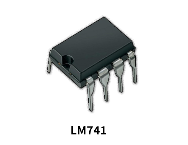
LM741 Pinout
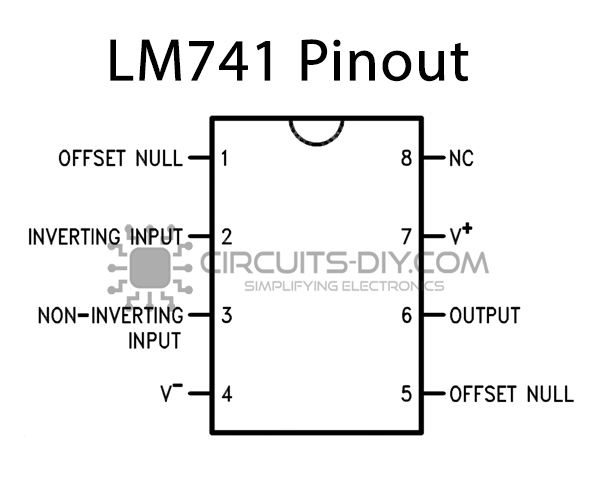
For a detailed description of pinout, dimension features, and specifications download the datasheet of LM741
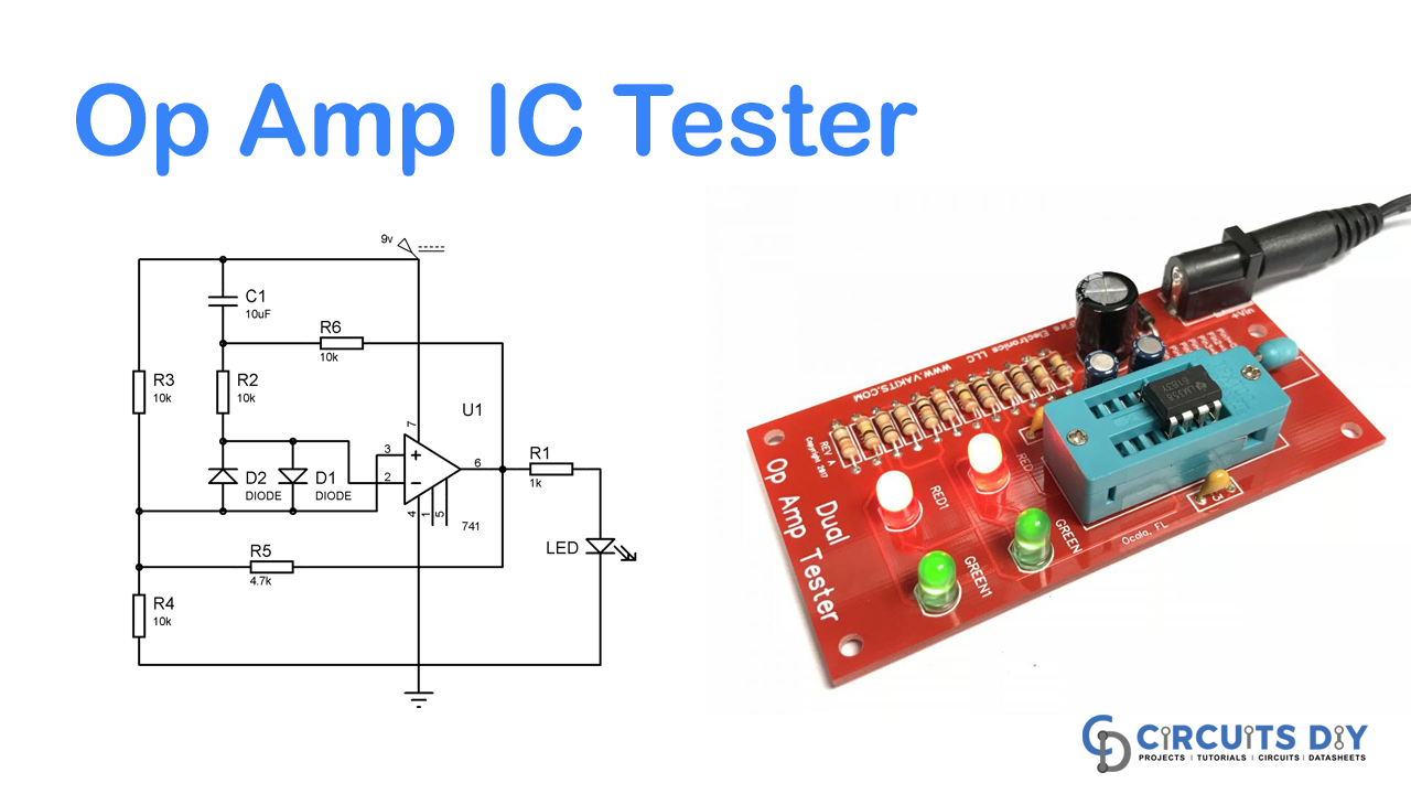
Op-Amp IC Tester Circuit

Working Explanation
If the op-amp LM741 is in a particular order, LEDs will flash or glow, but if the op-amp LM741 is inaccurate, either LED will stay ON or OFF perpetually.
Circuit operation is simple and induces a sine Wave at the outlet if the op-amp performs in a Flickering LED state. When the process lights up, the non-inverting input (+) voltage is first increased from the voltage at inverting input (-), and the output of the op-amp Lm741 (PIN 6) is stronger. This is the most critical aspect of the circuit. However, when C1 charging tries to reach the voltage at the inverted terminal (PIN 2), the output is low, and the capacitor C1 starts charging through the resistor R6. And when the output is smaller, the capacitor C1 begins to discharge, and the voltage on the comparator’s invert terminal is reduced, and the level is high. This phase frequently repeats and creates a sine wave at the output, leading to LED flickering.
So if Op-amp works, LED is flashed at a regular interval, and if the op-amp is defective, then the LED keeps either ON or OFF.
Applications and Uses
Circuit Op-amp IC Tester. Op-amp is a very critical feature of electronics that are used for different purposes in many electronic circuits. There has been an inaccuracy. The Op-amp has Voltage Comparator inside, one of which is inverted, and the feedback signal is non-inverted.