As we always want an electrical system without any faults, works properly, and we try to make sure the safety of everything that is linked to the system. So here the question is how we can find open earth phase neutral reverse in power source? For this purpose, we design a circuit by using simple components like resistors and LEDs. This circuit will provide LED indications and show if there’s a possible fault in the wiring of your home AC phase, neutral, and earth connections.
Hardware Required
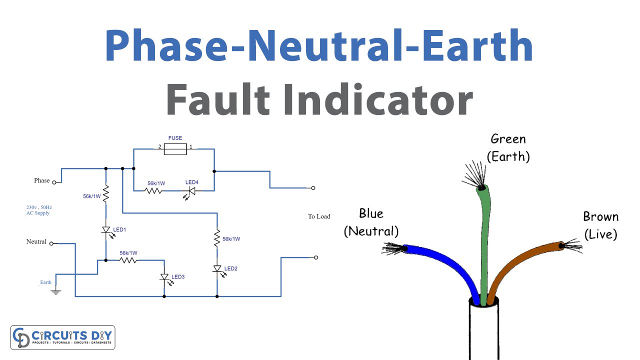
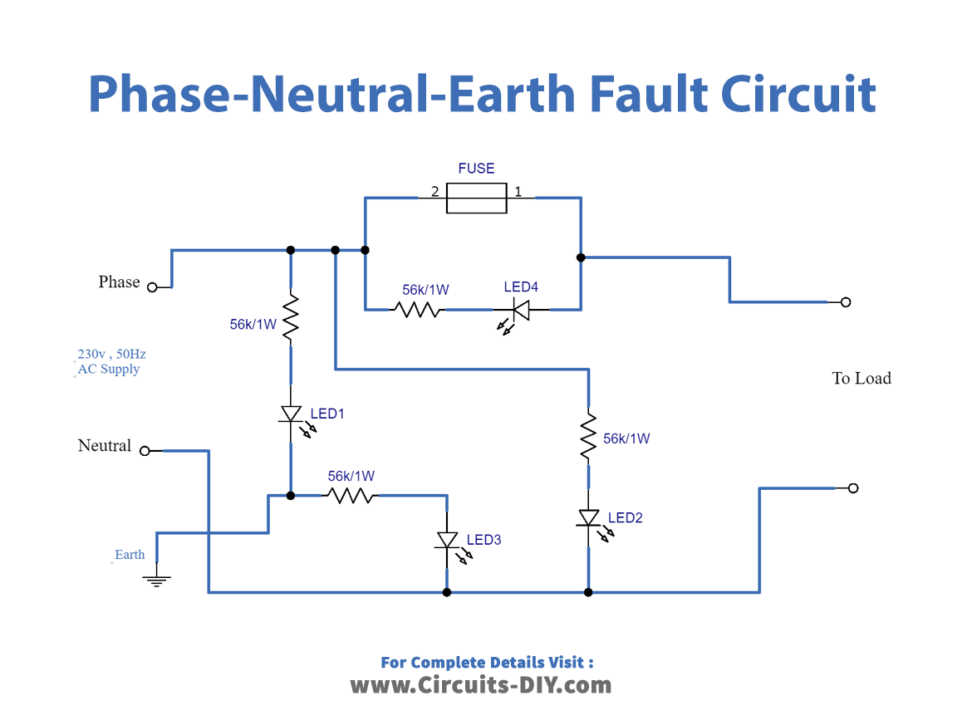
Circuit Diagram
Working Explanation
In this circuit, we have used four red color LEDs, and 56KΩ / 1W resistors. Here LED1 is connected between phase and earth through a resistor, you can connect LED in any polarity. And LED2 is connected between phase and neutral, further LED3 is connected between earth and neutral. These three LEDs will show the condition of the AC power supply. Now LED 4 is connected parallel to the fuse, this glows when the fuse is blown and the appliance is connected to the power source. To protect appliances from high voltage and surge current, some spike and surge protectors use MOV (Metal Oxide Varistor) along with this kind of circuit. To test the circuit for proper functioning, check the input supply at TP1 with respect to TP0. Also, check the voltage difference across neutral and earth pins as per the test point table.
Applications
Used to detect faults in earth phase neutral at homes, offices, and malls.