Introduction
The term “Radiofrequency” refers to the use of electromagnetic radiation to convey data between two circuits that are not connected electrically. Radiofrequency (RF) signals have a wide range of applications in electronics and telecommunication. Thus, the designers have made circuits and devices that can detect RF signals. So, we have decided that in this tutorial, we are going to make an “RF signal detector circuit”.
This is a device that detects electromagnetic signals between other devices in a certain area. RF signal detectors can be used to develop and test electrical radio frequency circuits in addition to the core detection applications.
Hardware Components
The following components are required to make RF Signal Detector Circuit
| S.no | Component | Value | Qty |
|---|---|---|---|
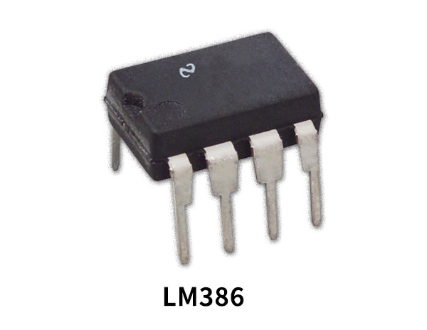
| 1. | IC | LM386 | 1 |
| 2. | Transistor | BC550 | 1 |
| 3. | Diode | 1N4148 | 2 |
| 4. | Speaker | 8Ω | 1 |
| 5. | LED | – | 1 |
| 6. | Antenna | – | 1 |
| 7. | Switch | – | 2 |
| 8. | Electrolyte Capacitor | 470uF/25V | 2 |
| 9. | Ceramic Capacitor | 0.33uF | 5 |
| 10. | Resistor | 1K, 10K, 680K, 10 ohms | 3, 1, 1, 1 |
| 11. | 2-Pin Connector | – | 1 |
LM386 Pinout
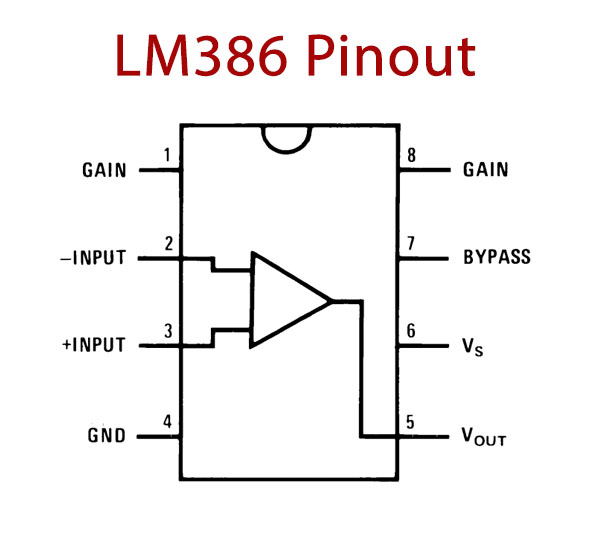
For a detailed description of pinout, dimension features, and specifications download the datasheet of LM386
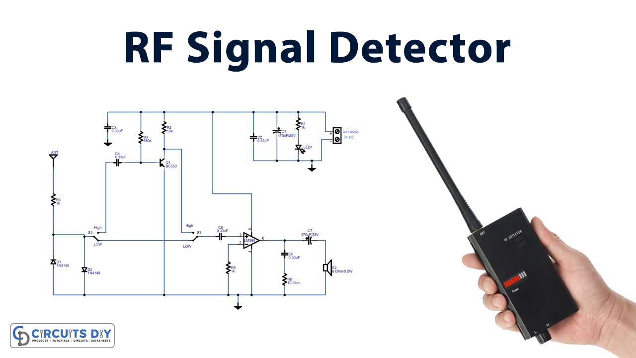
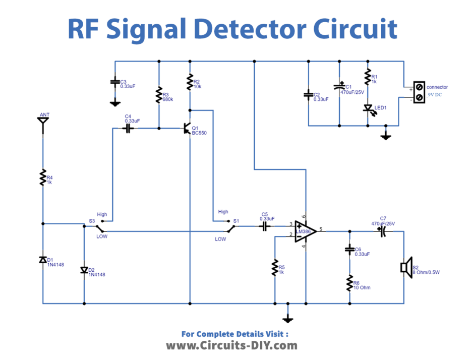
RF Signal Detector Circuit
Working Explanation
To make the RF signal detector circuit, you need to pre-amplify the noise signal which is produced with the help of an LM386 operational amplifier and a BC550 transistor pre-amplifier. While the circuit detects RF noise, the speaker is wired to the output of the op-amp provides an aural indication. This circuit runs on a 9V DC power supply, but you can also use a battery to power it. The SW1 and SW2 switches are utilized to switch this circuit’s detecting mode between low RF noise and high RF noise.
Application and Uses
- It can help to detect the presence of RF signal noise.
- It can be used in GPS locator detection devices.
- In wireless systems to detect and manage RF power