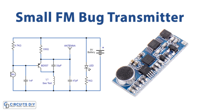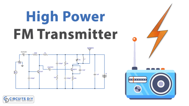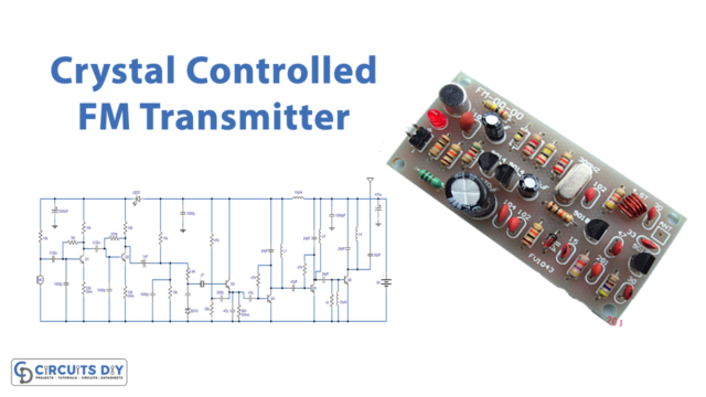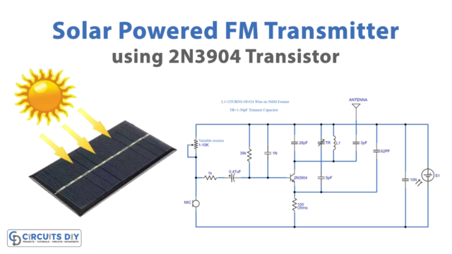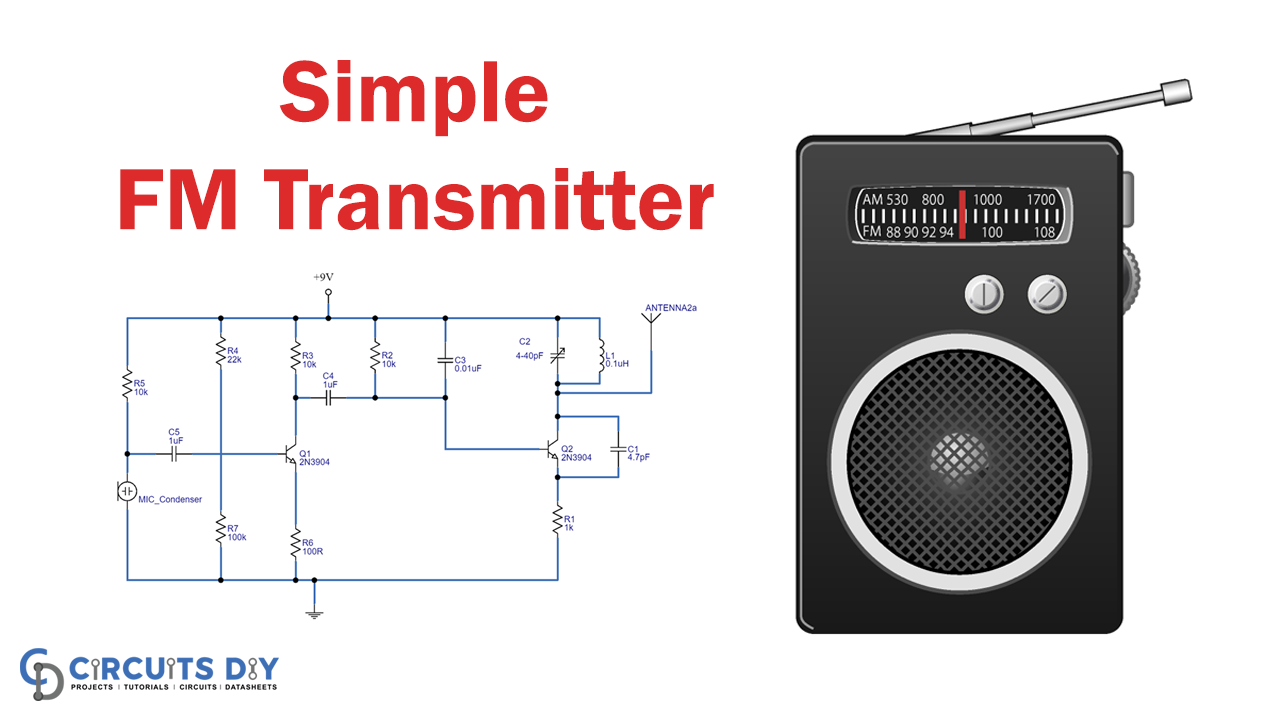
In telecommunication, frequency modulation (FM) transfers information by varying the frequency of the carrier wave according to the message signal. This is a low-power transmitter and it uses FM waves for transmitting the sound, this transmitter transmits the audio signals through the carrier wave by the difference of frequency. The carrier wave frequency is equivalent to the audio signal of the amplitude and the FM transmitter produces a VHF band of 88 to 108MHZ. Here we design a simple FM transmitter circuit with few easily available components.
Hardware Required
| S.No | Components | Value | Qty |
|---|---|---|---|
| 1 | Transistor | 2N3904 | 1 |
| 2 | Condenser MIC | – | 1 |
| 3 | Gang capacitor (Variable Capacitor) | 4 to 40pF | 1 |
| 4 | Capacitor (Disc Type) | 1uF | 2 |
| 5 | Capacitor | 0.01uF, 4.7pF | 1,1 |
| 6 | Resistor | 10KΩ, 22KΩ,100KΩ,100Ω,1KΩ | 3,1,1,1,1 |
| 7 | Inductor | 0.1uH | 1 |
| 8 | Connecting Wires | – | – |
| 9 | Battery | 9V | 1 |
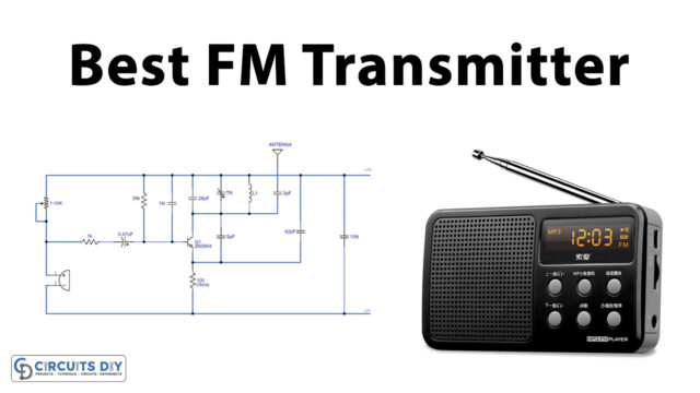
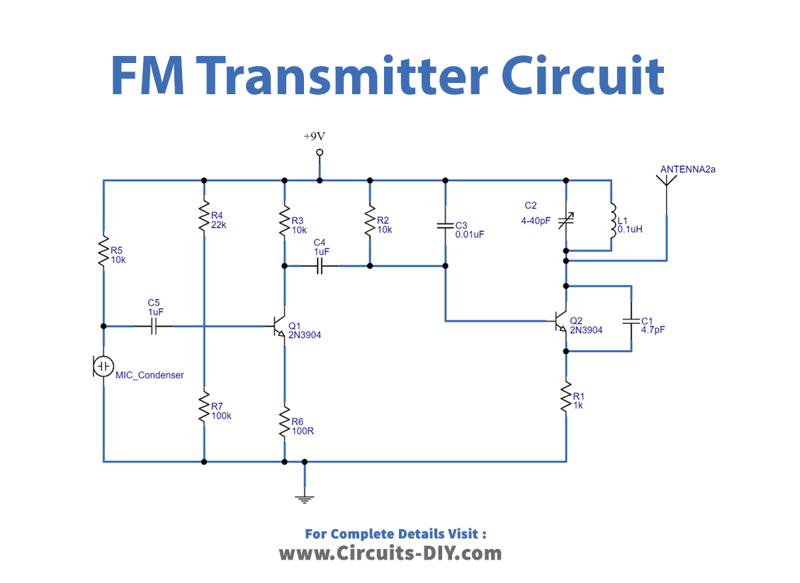
Circuit Diagram
Working Explanation
As we can see, this circuit consists of two transistors and a condenser mic. Here the condenser mic converts the voice signal into an audio signal and transistor Q2 amplifies the audio (message) signal. The Q1 transistor is placed here to produce carrier frequency. Now amplified audio(message) from the Q2 transistor is directly applied to the Q1 transistor base terminal. Hence the frequency of the carrier signal varies according to the audio (message) signal. In this way, we get the FM wave from the collector terminal of the Q1 transistor. This Frequency Modulation reaches several meters to kilometers with a low-power transmitter circuit. Here by using a lengthy monopole antenna, we can transmit FM waves up to several kilometers.
Applications
- The FM transmitters are used in the homes like sound systems in halls to fill the sound with the audio source.
- These are also used in cars and fitness centers. The correctional facilities have used FM transmitters to reduce the prison noise in common areas.