In this tutorial, we are going to make a “Square Wave Pulse Generator Circuit”.
In digital circuits, we need an external square pulse as a clock signal or carrier signal. Pulses can make the voltage either more positive or more negative. Usually, the more positive voltage is called the high (ON) state and the more negative voltage is called the low (OFF) state. The square wave generator produces an output voltage with equal ON and OFF periods. We don’t need a complex circuit to produce a square pulse signal, here we design a simple Square Wave Pulse Generator Circuit by using IC 4047, IC 4047 is a dual inline package astable, monostable multivibrator,
In the Astable mode, the output waveform of 4047 IC fluctuates between high and low logic levels which is identical to the square wave. It has 14 functional pins, it can take up to 15V as bias and gives a peak-to-peak output pulse, this IC requires few external timing elements to produce square pulse output. This is called a low-power monostable, astable multivibrator.
Hardware Components
The following components are required to make Square Wave Pulse Generator Circuit
| S.no | Component | Value | Qty |
|---|---|---|---|
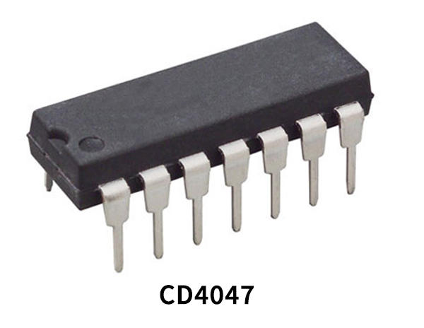
| 1. | IC | CD4047 | 1 |
| 2. | Variable Resistor | 1KΩ | 1 |
| 3. | Resistor | 200Ω, 100Ω | 1,1 |
| 4. | Ceramic Capacitor | 1nF | 1 |
| 5. | Connecting Wires | – | – |
| 6. | Power Supply | 12V | 1 |
CD4047 Pinout
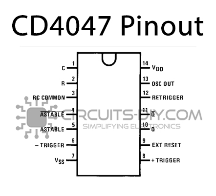
For a detailed description of pinout, dimension features, and specifications download the datasheet of CD4047
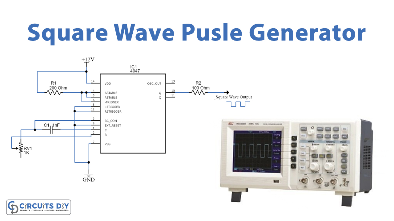
Square Wave Pulse Generator Circuit
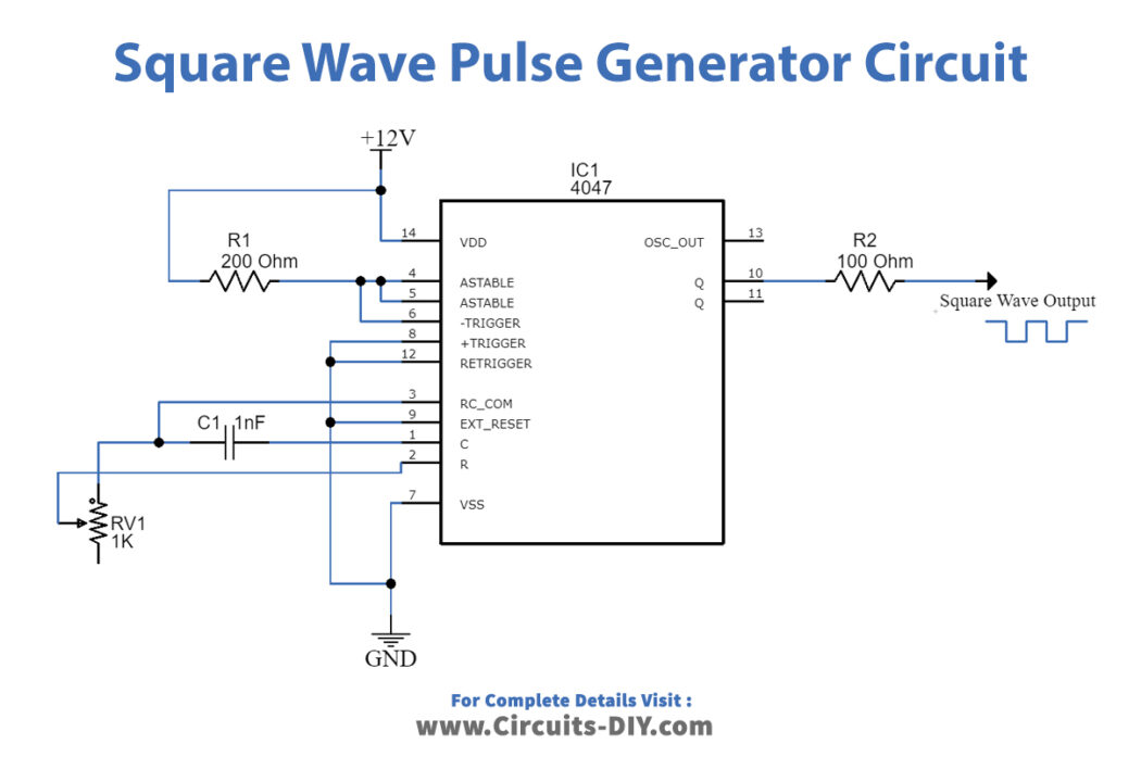
Working Explanation
This circuit requires a timing Resistor and timing capacitor with IC4047 to produce a monostable and astable output pulse. A resistor and capacitor are externally connected to PIN 2 and made short with PIN 3. The combination of resistor and capacitor (RC) generates output with a certain frequency. We supply an input voltage of 12V. Now output pulse amplitude can be controlled by connecting an external Resistor. Output terminal Q gives direct pulse and output terminal Q’ gives inverted output. The output for the square wave is taken from the PIN 10 in series with a 100-ohm resistor.
we can control the output mode and output pulse position and frequency to produce a calculated output pulse. And by this IC we cannot adjust the duty cycle, because it has a constant duty cycle of 50%. Thus, for controlling the frequency we have to vary the values of R and C in the circuit. By using a variable Resistor as a timing Resistor element, we can change the output square pulse frequency.
The formula for finding the value of frequency of Square Wave is given below:
f = 1 / 8.8RC
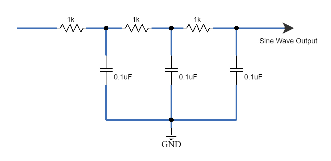
The square wave generated by this circuit can be easily converted into a Sine wave using a few resistors and capacitors.
Sine Wave Output
This Circuit is the modification of the above circuit for getting the Sinewave from a square wave. So, as we can see by connecting the Resistor capacitor network at the output, we can get sine wave output at the end. By changing the value of the network resistor and capacitor we can get different amplitude sine waves but the frequency will depend on the IC 4047 output square pulse.
Applications
- This can be used as a clock pulse for some of the ICs which need a clock pulse to operate.
- This is mainly used in the Inverter circuit to generate Alternating current from DC.
- Can be used in frequency discriminators, timing circuits, time-delay applications, Envelope detection, frequency multiplication, and frequency division.