In this Tutorial, we are going to make a “Signal amplifier circuit diagram with a set input-output ratio”. A signal amplifier is a circuit that utilizes electrical energy to boost the voltage or current of an incoming signal and output this stronger version at its output terminals. The perfect signal amplifier produces a signal that is bigger but otherwise similar to the original signal.
In the making of the circuit, we are using LF351 IC. The LF351 is an operational amplifier with an input offset voltage that is internally compensated. The IC has a broad bandwidth, a low input bias current, and a low offset current.c
Hardware Required
| S.no | Component | Value | Qty |
|---|---|---|---|
| 1. | IC | LF351 | 1 |
| 2. | Diode | 1N4148 | 4 |
| 3. | Variable Resistors | 50K | 1 |
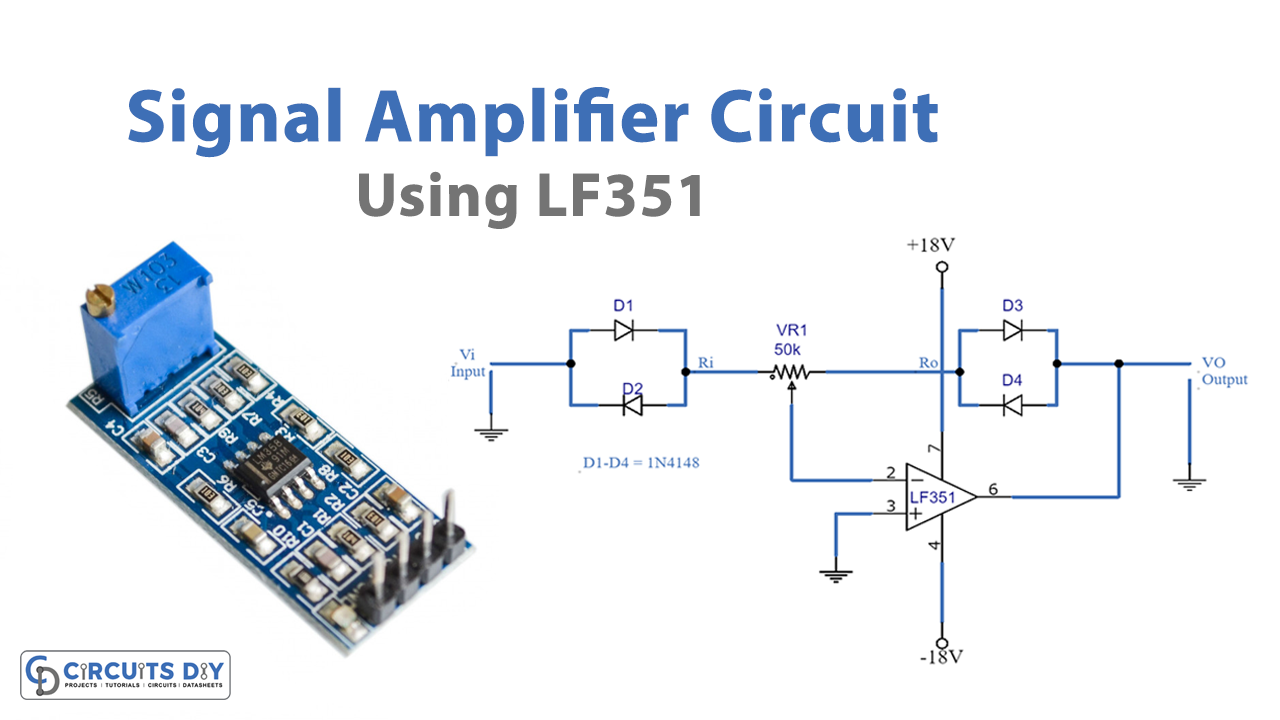
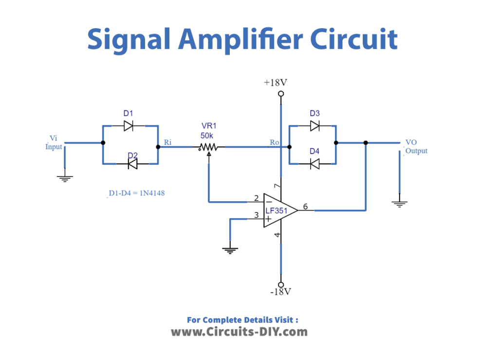
Circuit Diagram
Working Explanation
This Signal Amplifier Circuit determines the input/output ratio. The op-amp (IC1) is used as a signal amplifier. And some signals will be sent back through the diode, which has a potentiometer-VR1 with a resistance of roughly 50 km. Three distinct models are used to choose the output signal.
The silicon diode operates in a high-sensitivity switching mode. The power supply is therefore dependent on the amplifier circuit, which employs op-amp types. In the circuit, the OP-AMP number LF351 has a JFET as the input of the amplifier section, resulting in a low noise signal. We can utilize power supplies ranging from +9V to +18V. We can substitute Potentiometer in series with fixed resistors
If you rotate potentiometer VR1 clockwise until the input impedance or Ri is about 12Kohms, the output impedance or Ro is around 36Kohms, and the ratio between signal input and output is exponential, or if Ri is equal to Ro or approximately 24 Kohms, the output is linear. And if Ri is 36 Kohms and Ro is 12 Kohms, the output is in logarithmic form. As shown in the graph below,

Application Uses
- Communication systems
- Signal amplification
- In Opamps, etc