There are millions of active cellular devices that are in active use in today’s day & age. Although the advent of mobile phones has given us a lot of opportunities in terms of effective communication technology, there are several instances where individuals tend to abuse this device & the need to properly regulate the usage of cellular devices in such situations becomes imperative. So, in this project, we are going to look into a step by step procedure on ‘How To Make A Mobile Signal Jammer’ using just a single PNP transistor & a small number of other components.
JLCPCB is the foremost PCB prototype & manufacturing company in china, providing us with the best service we have ever experienced regarding (Quality, Price Service & Time).
What is a Mobile Signal Jammer?
A Mobile signal jammer is an electronic device that blocks the transmission of signals between a cell phone and a base station. By using the same frequency as a mobile handset, the cell phone jammer creates strong interference for communication between the caller and receiver. It is effective in blocking the transmission of signals from networks including UMTS, 3G, CDMA, GSM, and PHS.
Hardware Components
You will need the following parts to build this project.
| S.no | Component | Value | Qty |
|---|---|---|---|
| 1. | PNP transistor | BF454 | 1 |
| 2. | Ceramic Capacitors | 1uF, 102pF, 15pF, 4.7pF, 5pF | 8 |
| 3. | Push Button | – | 1 |
| 4. | Enameled Copper wires | – | 3 meters |
| 5. | Inductor | 22nH | 1 |
| 6. | Resistors | 100K, 39K | 2 |
| 7. | Soldering Iron | 45W-65W | 1 |
| 8. | Soldering Wire with Flux | – | 1 |
| 9.. | DC Battery with clip | 3.7V | 1 |
| 10. | Smartphone | – | 1 |
| 11. | Veroboard | – | 1 |
| 12. | Jumper Wires | – | As per ned |
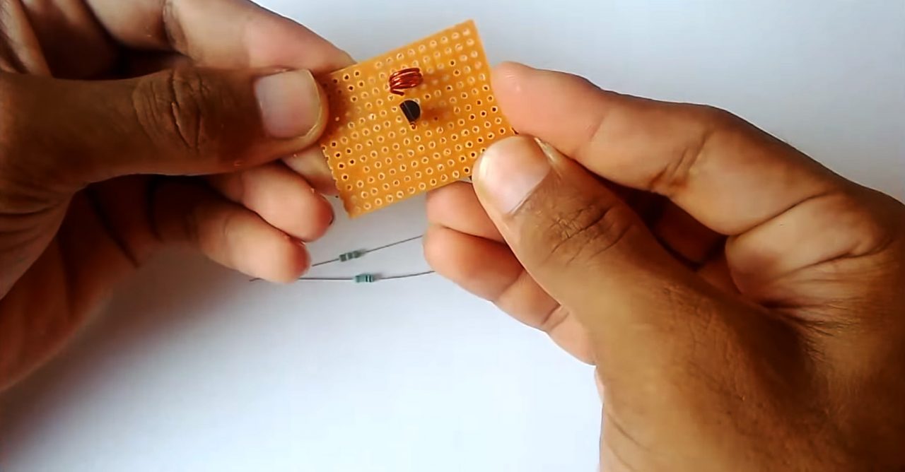
Useful Steps
1) Solder the BF494 transistor on the Vero board & solder a 22nH inductor to its collector pin.
2) Solder a 15nF capacitor on the collector of the BF494 to Vcc of the circuit.
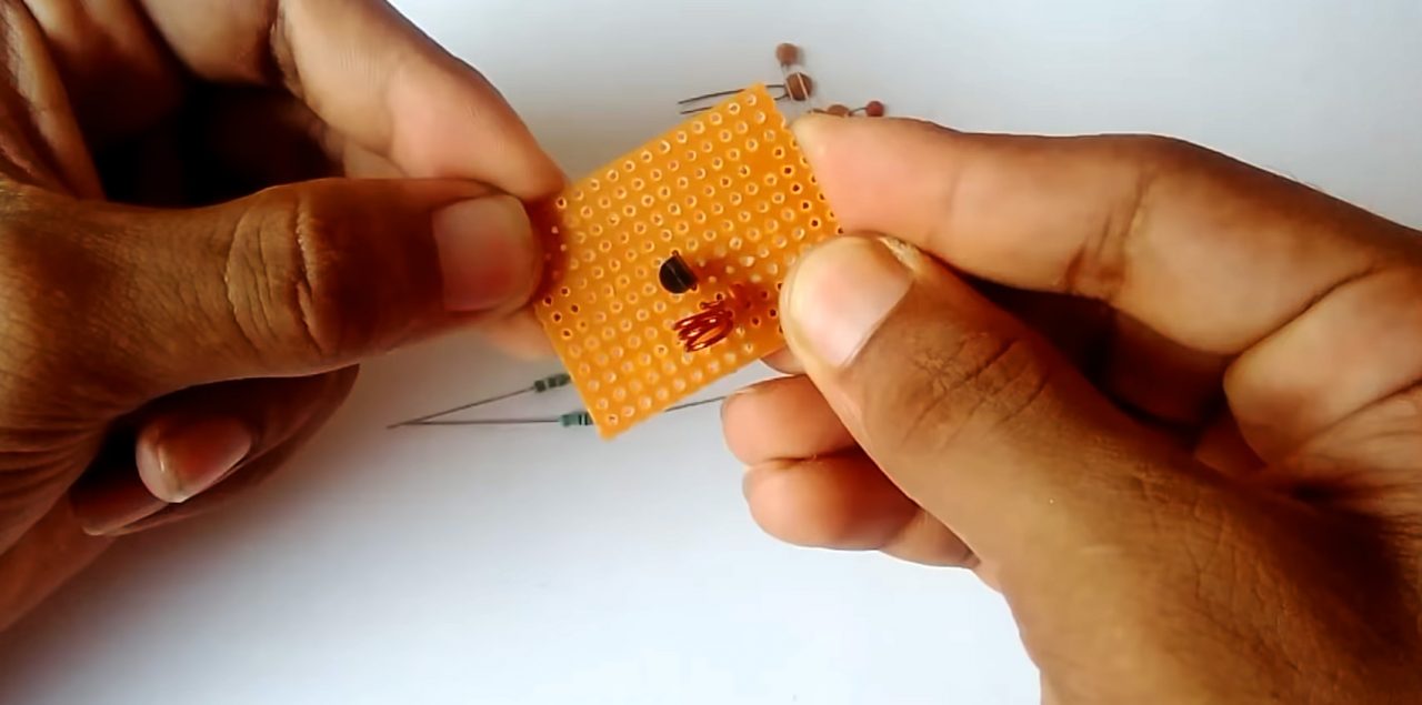
3) Solder the two 4.7pF capacitors in parallel between collector & emitter of the transistor.
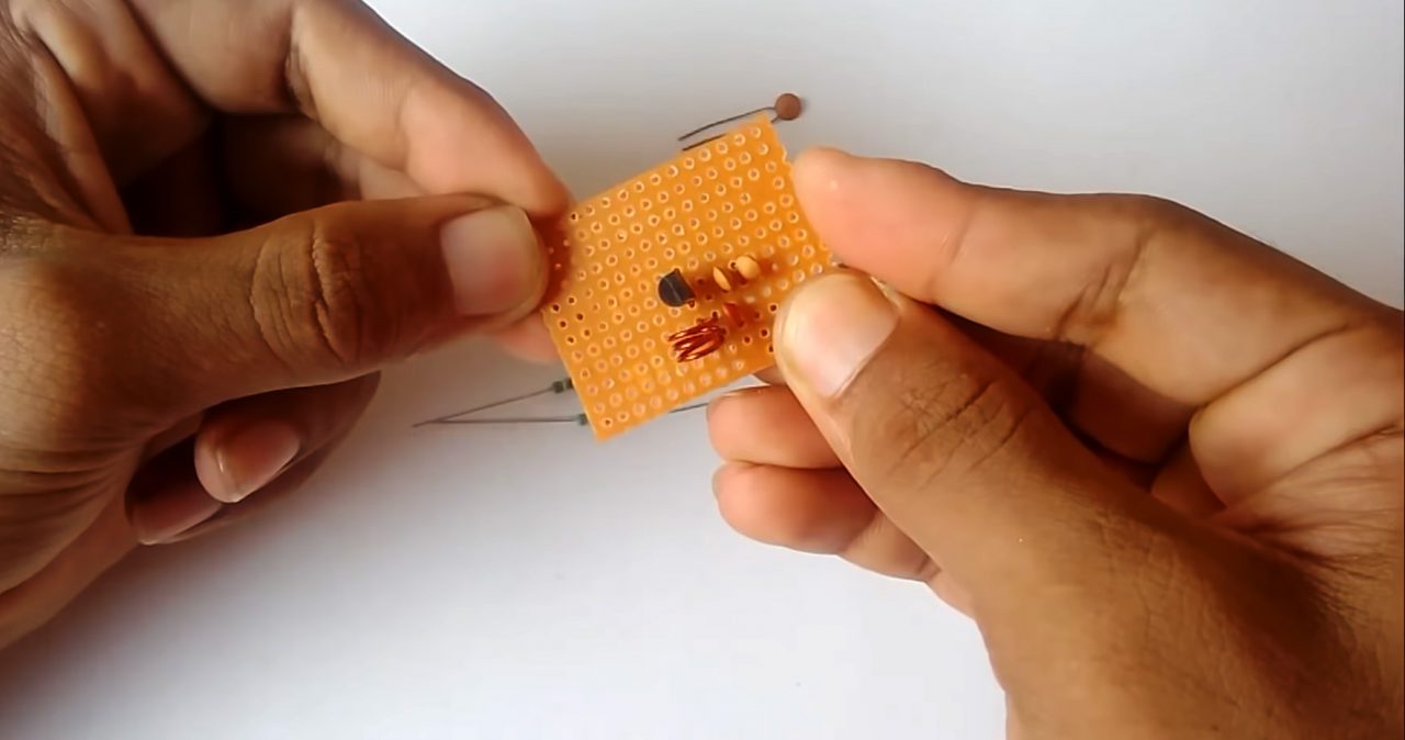
4) Solder a 39K Ohm resistor & a 102pF capacitor to the base of the transistor to VCC.
5) Solder a 1uF capacitor on base to collector of the transistor.
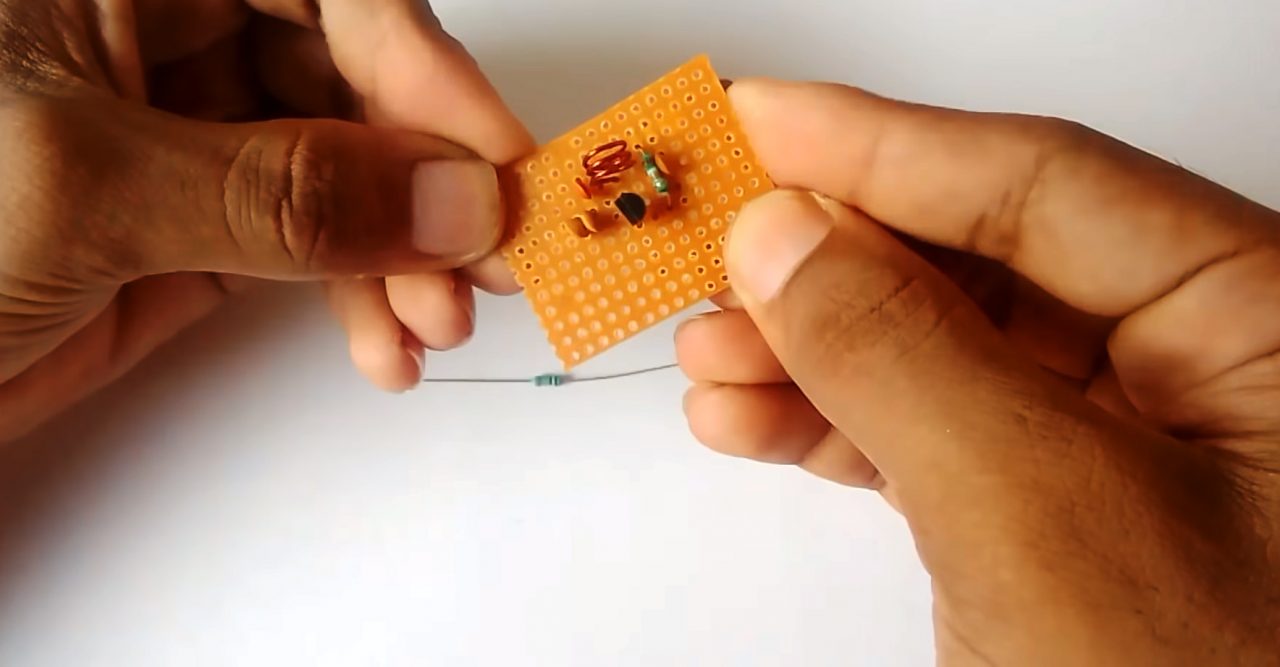
6) Solder a 100K resistor on the emitter of the transistor & two 5pF capacitors in series on Vcc to GND.
7) Connect a pushbutton with a 5pF capacitors to the +ve terminal of the DC Battery.
8) Connect a 3m coiled copper wire antenna to the 5pF capcitor.
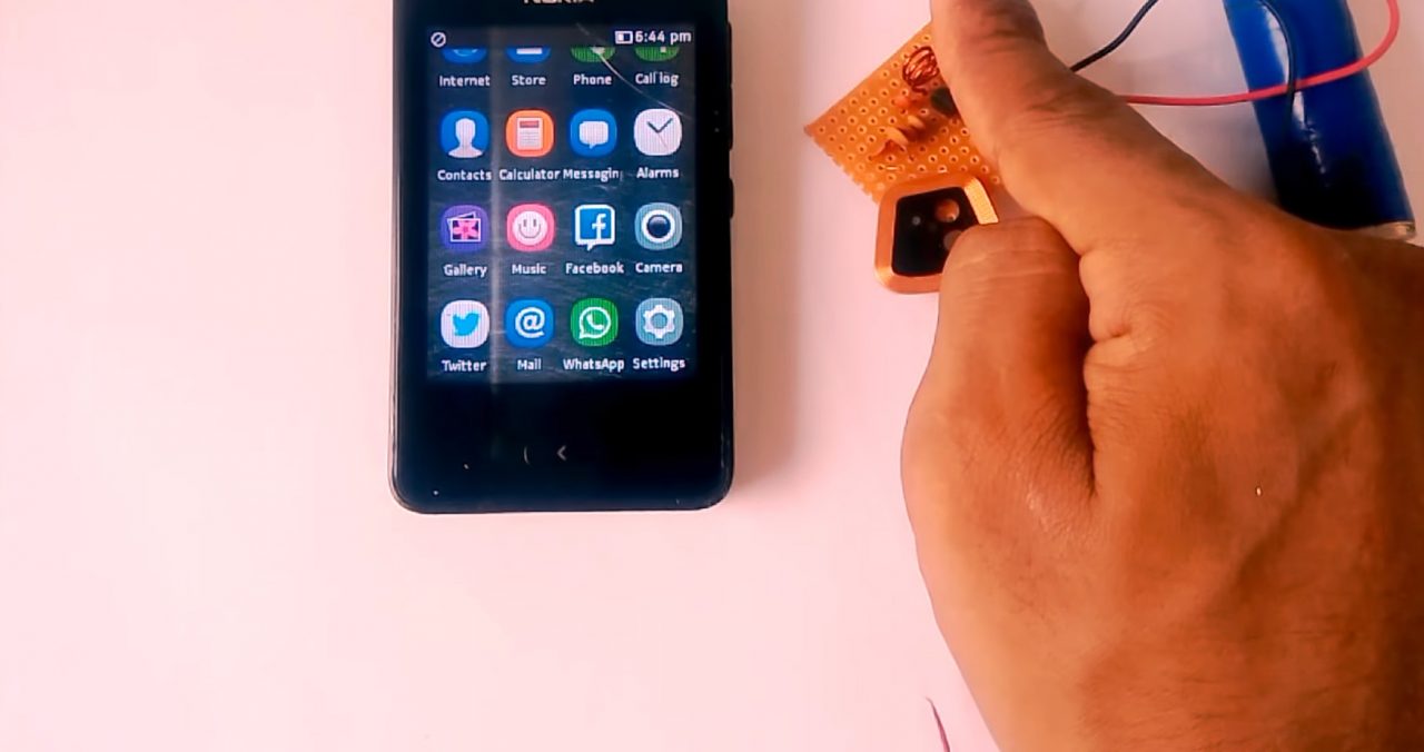
9) Power up the circuit & test the circuit by pressing the pushbutton.
Circuit Diagram For Mobile Signal Jammer
Working Explanation
The working of this circuit is actually pretty simple. The circuit generates signals at frequency bands as same as the mobile phone signal band, causing interference which results in a DoS (Denial of Service) attack; The jammer denies service of the radio spectrum of the cell phone users within range of the jamming device.
Applications
- Generally functions in areas where use of a cellular device is prohibited such as military installments & ATC testing sites.