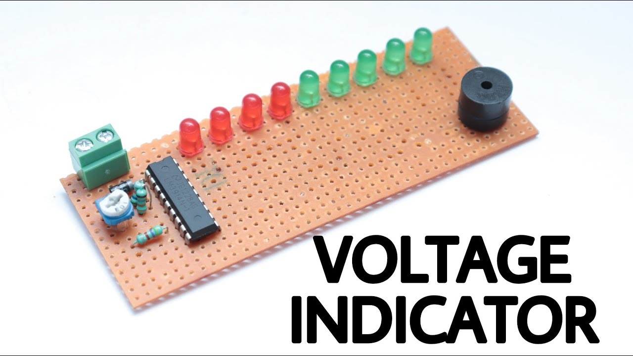
What is a Voltage Level Indicator?
A Voltage Level Indicator is a simple electronic circuit that can indicate the voltage level between any two nodes in a circuit. It is a simple yet crucial electronic circuit that later becomes the basis of many advanced testing equipment. It is easy to design and relatively inexpensive. So, In today’s article, we will learn how to design a basic Voltage level Indicator circuit using an LM3914 Dot/Bar Display Driver IC & a small number of other components.
LM3914 is an analog-controlled LED driver IC. This IC eliminates the need for programming a microcontroller and also reduces the hardware required to control 10 LEDs. For LM3914, the input voltage can vary from 3V to 18V. The IC has two operating modes DOT mode and BAR mode, also more than one IC can be cascaded to control up to 100 LEDs. Since the LEDs can be controlled without any flickering and perform flawlessly with equal brightness these ICs are commonly used in visual alarms and other metering or monitoring applications.
JLCPCB is the foremost PCB prototype & manufacturing company in china, providing us with the best service we have ever experienced regarding (Quality, Price Service & Time).
Hardware Components
The following components are required to make Voltage Level Indicator Project
| S.no | Component | Value | Qty |
|---|---|---|---|
| 1. | LED Driver IC | LM3914 | 1 |
| 2. | LEDs | 5mm, 3.5V | 9 |
| 3. | Piezo Buzzer | 3V | 1 |
| 4. | Potentiometer | 10K | 1 |
| 5. | Diode | 1N4007 | 1 |
| 6. | Resistors | 56K, 18K, 4.7K | 1 |
| 7. | Variable Power Supply | DC, 12V | 1 |
| 8. | Soldering Iron | 45W – 65W | 1 |
| 9. | Soldering Wire with Flux | – | 1 |
| 10. | Terminal Block Connector | – | 1 |
| 11. | Multimeter with probes (Optional) | – | 1 |
| 12. | Veroboard | – | 1 |
| 13. | Jumper Wires | – | As per need |
LM3914 Pinout
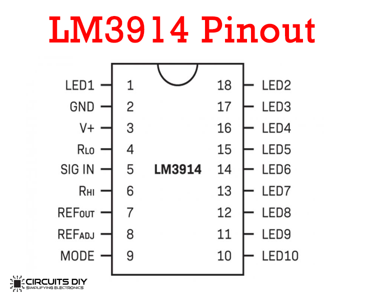
For a detailed description of pinout, dimension features, and specifications download the datasheet of LM3914
Useful Steps
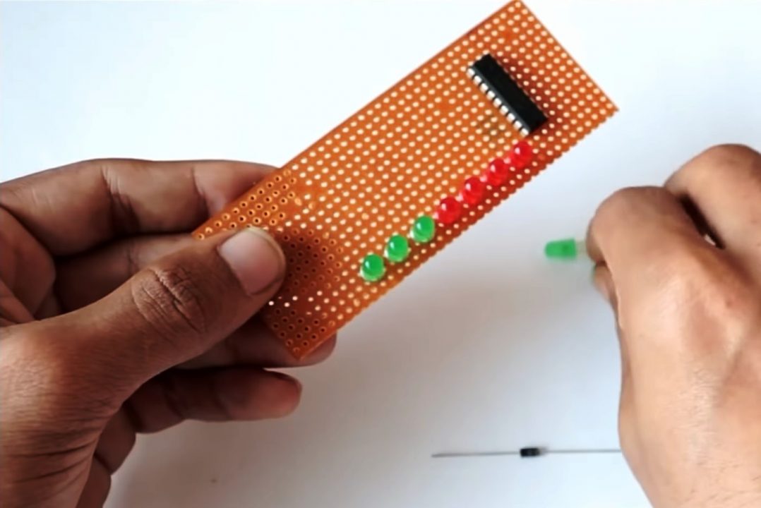
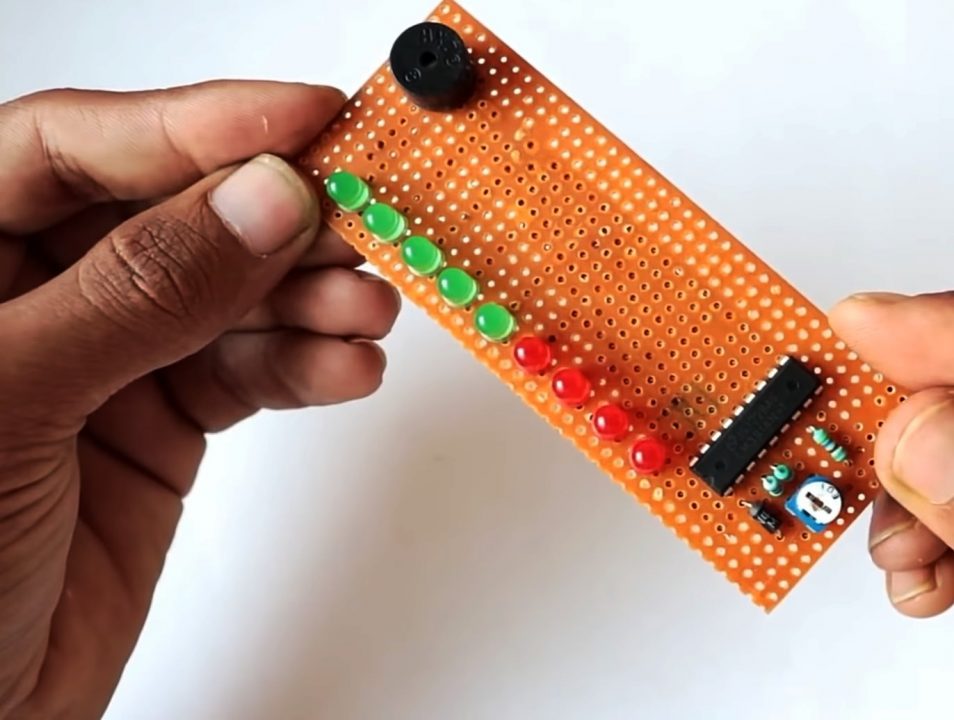
1) Solder the LM3914 IC on the Veroboard. After that, Solder the -ve terminals of the nine LEDs with pins 1, 18, 17, 16, 15, 14, 13, 12, and pin 11 of the LM3914 IC
2) Solder the -ve terminal of the 3V piezo buzzer with pin 10 of the IC. After that, Solder the 18KOhm between Pin 4 & Pin 2 of the IC.


3) Solder the middle pin (variable end) of the 10K preset pot with pin 5 of the IC & one of the fixed ends with pin 2 of the IC.

4) Solder a 56KOhm resistor between pin 3 of the IC & remaining fixed end of the preset 10K pot.
5) Now solder the 4.7KOhm resistor with Pin 6 & 7 of the IC & short the other end of the resistor with pin 2 & 8 of the IC.

6) Solder the cathode of the 1N4007 with Pin 3 & 9 of the IC. After that, solder the anode of the diode with the +ve terminals of all the LEDs & the buzzer.
7) Solder the -ve terminal of the block connector with Pin 2 & 8 of the IC & the +ve terminal with pin 9 & 3 of the IC.

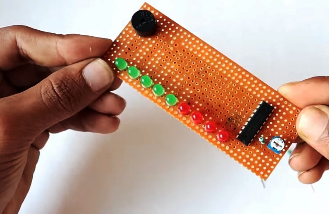
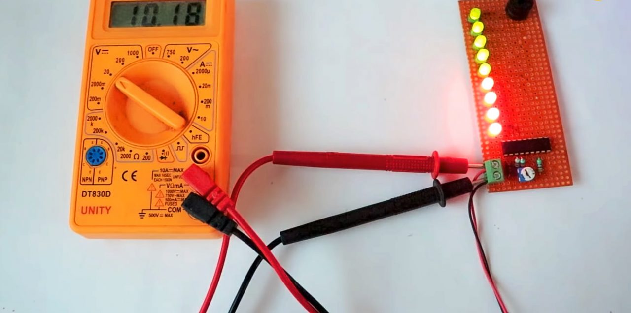
8) Power up the circuit using a variable DC supply & test the circuit.
Voltage Level Indicator Circuit
Working Explanation
The working of this circuit is as follows. On connecting a DC power input to the block connector terminal of the circuit, The DC input enters the SIGNAL pin of the IC. This signal goes through the LM3914 integrated comparator. The LM3914 comparator glows the LEDs with respect to the increasing/decreasing strength of the signal from the variable DC power supply. The reference voltage at Pin 7 is set by a resistor (4.7K). You can adjust the sensitivity of the LEDs by tuning the 10K preset pot.
The IC can operate in two different modes, one is the dot mode and the other is bar mode. In Dot mode, the MODE pin (pin 9) is open by using a toggle switch, in this mode, only one LED will turn on depending on the input voltage from the DC source. In Bar mode, the mode pin (pin 9) connects to the V+ pin and the LED will turn on or turn off sequentially based on the input voltage.
Applications
- Most commonly used in the music industry for procedures such as live music production & recording.