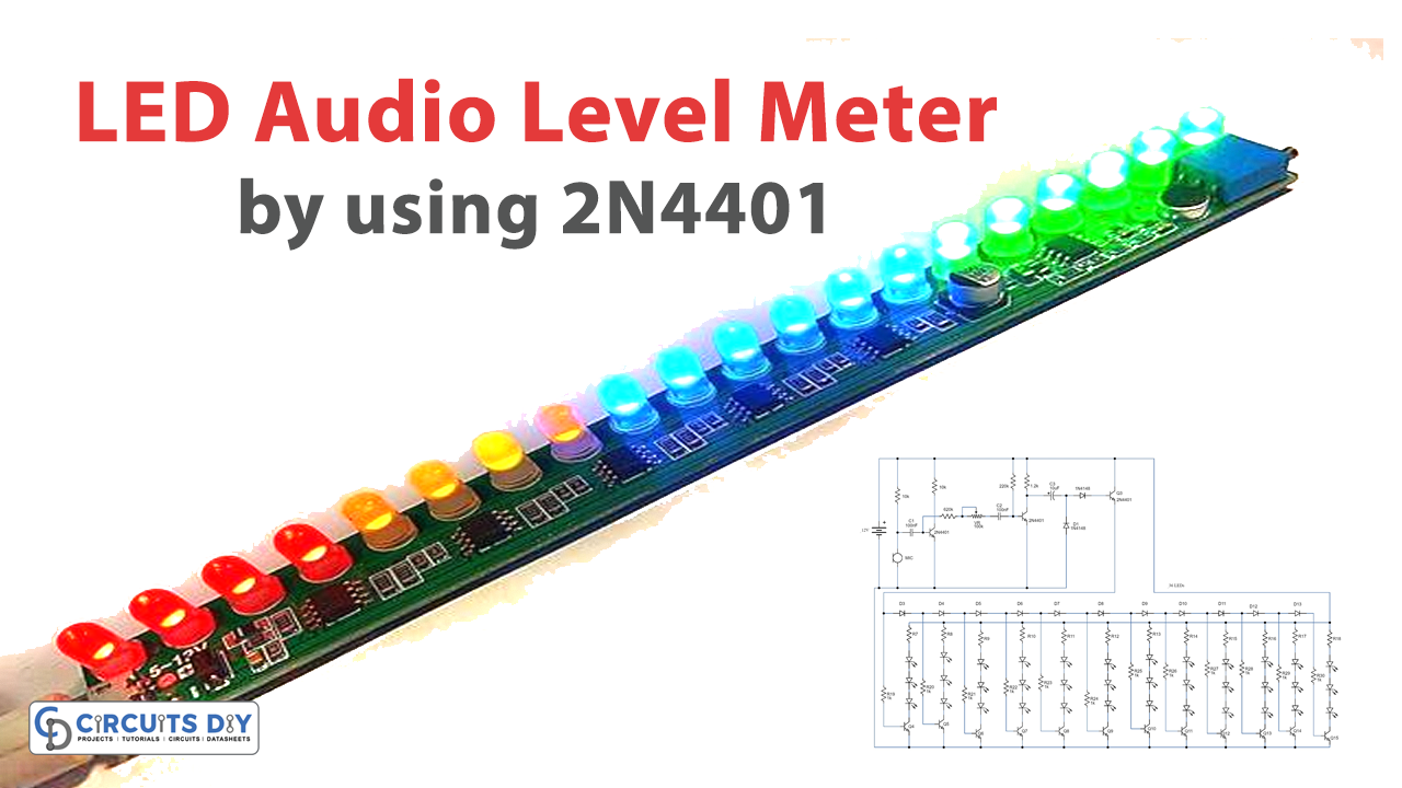
An LED audio level meter is an electronic testing device that shows the intensity level of any audio signal with respect to its audio amplitude. It has become an essential piece of electronic testing equipment for procedures such as signal intensity and quality analysis in Audio Studios & lives music production and recording sets. So, in this project, we are going to design a LED Audio Level Meter Using 2N4401 NPN Transistors.
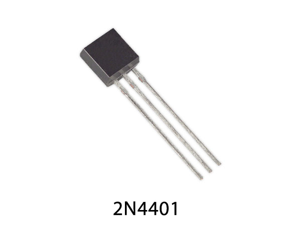
2N4401 is an NPN transistor hence the collector and emitter will be left open (Reverse biased) when the base pin is held at the ground and will be closed (Forward biased) when a signal is provided to the base pin. 2N4401 has a gain value of 500; this value determines the amplification capacity of the transistor. The maximum amount of current that could flow through the Collector pin is 800mA. To bias this transistor we have to supply current to its base pin, this current (IB) should be limited to 5mA.
Hardware Components
The following components are required to make Audio Level Meter Circuit
| S.no | Component | Value | Qty |
|---|---|---|---|
| 1. | NPN Transistor | 2N4401 | 15 |
| 2. | Electret mic | – | 1 |
| 3. | LEDs | 5mm/25mA | 36 |
| 4. | Diodes | 1N4148 | 13 |
| 5. | Potentiometer | 100K | 1 |
| 6. | Electrolytic Capacitor | 10uF/25V | 1 |
| 7. | Ceramic Capacitor | 100nF | 2 |
| 8. | Resistors | 620K, 220K, 10K, 5.1K, 1.2K, 75Ohms | 29 |
| 9. | DC Power Supply | 12V | 1 |
| 10. | Breadboard | – | 1 |
| 11. | Connecting Wires | – | As per need |
2N4401 Pinout
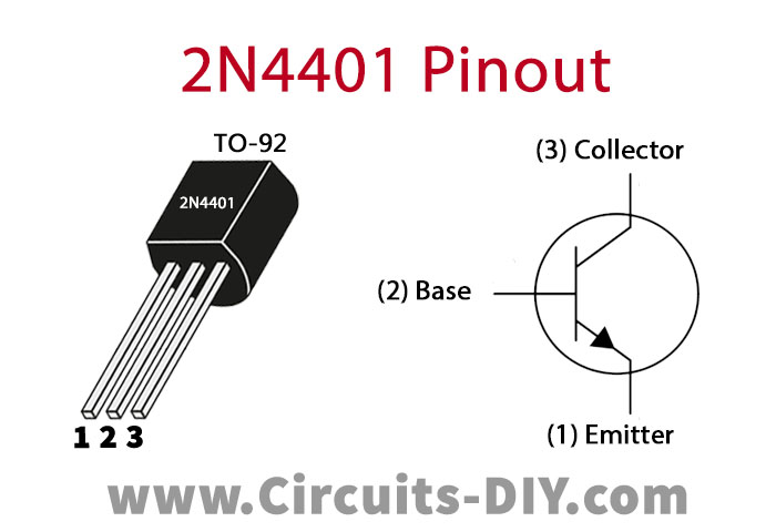
For a detailed description of pinout, dimension features, and specifications download the datasheet of 2N4401
Audio Level Meter Circuit

Working Explanation
This circuit uses an electret mic to detect Audio and reflects its intensity using LEDs. The working of this circuit is pretty simple, an audio transducer (electret microphone) sends the audio signal to the base of transistor Q1. Here a capacitor (100nF) blocks the DC component of the signal, allowing the AC signal to move on. these electrical audio signals are then amplified by the transistors Q1 and Q2. The amplified audio signals at the collector of the transistor Q2 pass through a 10uF filter capacitor and get rectified by diodes D1 and D2. These DC signals are fed to the base of the transistor Q3, switching it ON. The transistor Q3 also controls transistors Q4 to Q15 according to the DC signals received from the diodes D1 and D2. Thus LEDs glow corresponding to the amplitude of the input audio signal.
The audio detection sensitivity of this circuit can be tuned by using a 100K Pot. This circuit can be operated by using a 12V DC Power Supply
Applications
- Mostly works as an audio signal intensity analysis instrument in live music production and recording.
- Used for displaying the sound level of various microphones, speakers, and power-amps.