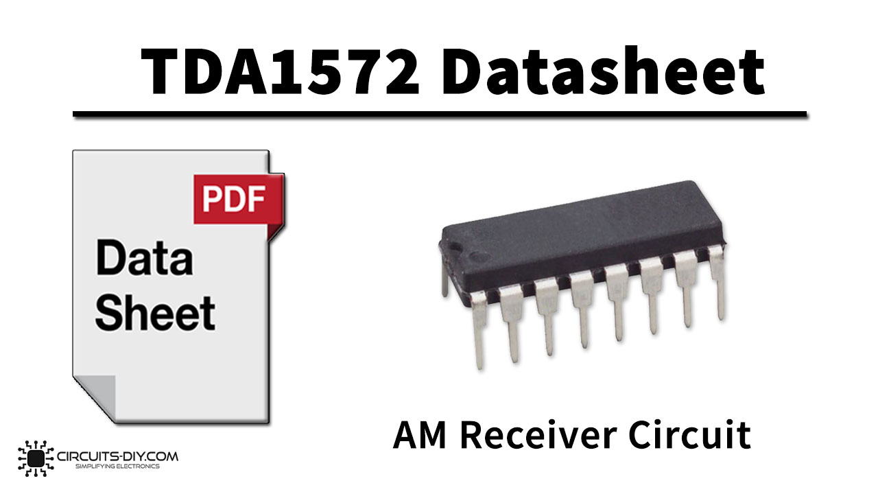
The TDA1572T integrated AM receiver circuit performs all the active functions and part of the filtering required of an AM radio receiver. It is intended for use in mains-fed home receivers and car radios. The circuit can be used for oscillator frequencies up to 50 MHz and can handle RF signals up to 500 mV. RF radiation and sensitivity to interference are minimized by an almost symmetrical design. The controlled-voltage oscillator provides signals with extremely low distortion and high spectral purity over the whole frequency range, even when tuning with variable capacitance diodes. If required, band switching diodes can easily be applied. Selectivity is obtained using a block filter before the IF amplifier.
Functional Description
Gain-controlled RF stage and mixer
The differential amplifier in the RF stage employs an AGC negative feedback network to provide a wide dynamic range. Very good cross-modulation behavior is achieved by AGC delays at the various signal stages. Large signals are handled with low distortion and the (S + N)/N ratio of small signals is improved. Low noise working is achieved in the differential amplifier by using transistors with low base resistance
Oscillator
The differential amplifier oscillator is temperature compensated and is suitable for simple coil connection. The oscillator is voltage-controlled and has little distortion or spurious radiation. It is specially suitable for electronic tuning using variable capacitance diodes. Band switching diodes can easily be applied using the stabilized voltage V15-20. An extra buffered oscillator output (pin 14) is available for driving a synthesizer. If this is not needed, resistor RL(14) can be omitted.
TDA1572 Pinout
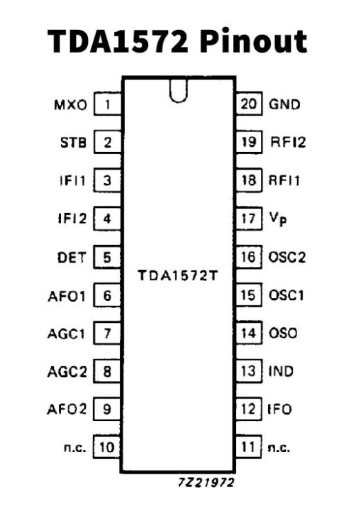
TDA1572 Pin Configuration
| Pin No | Pin Name | Description |
|---|---|---|
| 1 | MXO | Mixer Output |
| 2 | STB | Standby Switch |
| 3 | IFI1 | IF Input 1 |
| 4 | IFI2 | IF Input 2 |
| 5 | DET | Detector |
| 6 | AFO1 | AF Output 1 |
| 7 | AGC1 | AGC Stage 1 |
| 8 | ACG2 | AGC Stage S |
| 9 | AFO2 | AF Output 2 |
| 10 | N.C | No Connection |
| 11 | N.C | No Connection |
| 12 | IFO | IF Output |
| 13 | IND | Indicator Output |
| 14 | OSO | Buffered Oscillator Output |
| 15 | OSC1 | Oscillator 1 |
| 16 | OSC2 | Oscillator 2 |
| 17 | VP | Supply Voltage |
| 18 | RFI1 | RF Input 1 |
| 19 | RFI2 | RF Input 2 |
| 20 | GND | Ground |
TDA1572 Features
- Inputs protected against damage by static discharge
- Gain-controlled RF stage
- Double balanced mixer
- Separately buffered, voltage-controlled and temperature-compensated oscillator, designed for simple coils
- Gain-controlled IF stage with wide AGC range
- Full-wave, balanced envelope detector
- Internal generation of AGC voltage with possibility of second-order filtering
- Buffered field strength indicator driver with short-circuit protection
- AF preamplifier with possibilities for simple AF filtering
- Electronic standby switch
- IF output for stereo demodulator and search tuning
Application
You can download this datasheet for TDA1572 AM Receiver Circuit from the link given below: