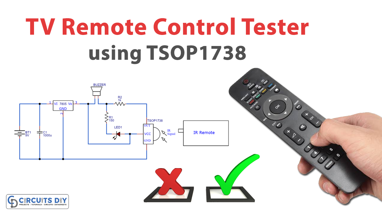
Remote control devices are usually based upon one of two main types of technology: radio frequency (RF) technology or infrared (IR) technology. When it comes to televisions the dominant technology tends to be infrared. An Infrared TV remote uses light to transfer signals from the remote to the device it controls. The frequency at which most of the remotes work is around 38KHz.
Most of the time a dead battery or a loose battery connection causes the remote handset to malfunction. However, if you have a new battery installed and still the device doesn’t work efficiently then you can test it with a simple remote tester circuit. So in this tutorial, we will show you how to make a simple remote tester circuit at home by using some basic electronic components.
Hardware Components
The following components are required to make the Remote Control Tester Circuit
| S. No | Component | Value | Qty |
|---|---|---|---|
| 1. | IR Remote | – | 1 |
| 2. | Breadboard | – | 1 |
| 3. | Battery | 9v | 1 |
| 4. | Connecting Wire | – | 1 |
| 5. | IR Sensor | TSOP1738 | 1 |
| 6. | Regulator IC | LM7805 | 1 |
| 7. | Resistors | 1k, 150 ohms | 1, 1 |
| 8. | Capacitor | 1000uF | 1 |
| 9. | Buzzer | – | 1 |
| 10. | LED | 5mm | 1 |
TSOP1738 Pinout

For a detailed description of pinout, dimension features, and specifications download the datasheet of TSOP1738
LM7805
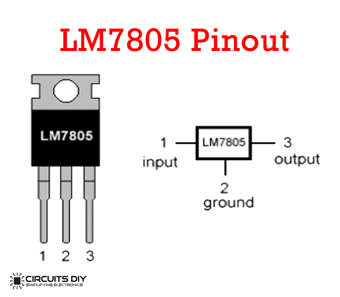
For a detailed description of pinout, dimension features, and specifications download the datasheet of LM7805
Remote Control Tester Circuit
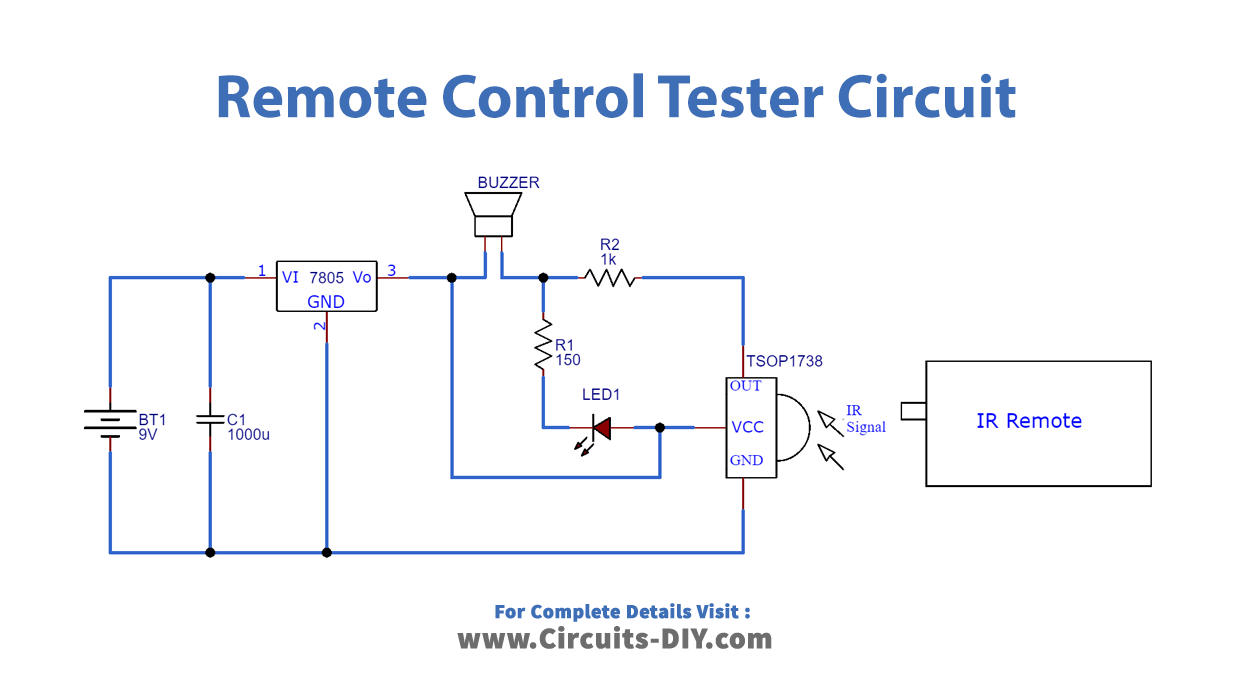
Connections
- Place the TSOP1738 IR Sensor on the breadboard and connect Pin 1 to GND.
- Connect Pin 2 to VCC and connect the output Pin 3 to LED and Buzzer.
- Place the LM7805 Voltage regulator on the breadboard and connect Pin 1 to VCC and Pin 2 to GND.
- Connect the output pin 3 to the LED and Buzzer.
- Connect the 1000uF Capacitor between VCC and GND.
Working Explanation
The IR sensor TSOP1738 has a PIN photodiode and a FET signal amplifier enclosed in an Epoxy case. The sensor requires 5 volts for its operation and its output is actively low. Normally its output gives + 5 volts and goes down to zero when it receives a pulse of 38 kHz. The output of TSOP1738 is connected to an LED and buzzer. When the remote handset is focused on the sensor and any button is pressed, the buzzer beeps, and the LED blinks indicating that the handset is working perfectly.
To provide 5V to the IR sensor TSOP1738 from a 9V battery, we will use an LM7805 voltage regulator. Pin 1 of the voltage regulator is connected to +9 Volts of the battery and the output Pin 3 is connected to the buzzer and LED. The 1000uF capacitor connected in parallel to the battery will reduce the flickering in the circuit.
Applications
- You can use this circuit to control the switching of relays with a remote. The relay can switch on or off the load connected to it
Related posts:
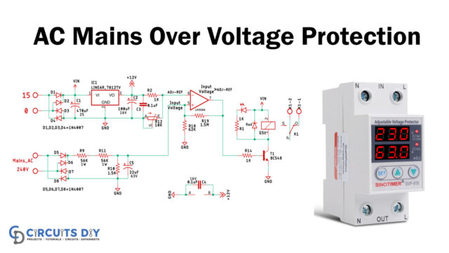 230V AC Mains Over Voltage Protection Circuit
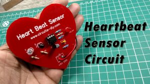 Heartbeat Sensor Circuit Using LM358 - Electronics Projects
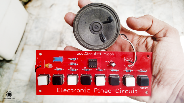 Electronic Piano Circuit using 555 Timer
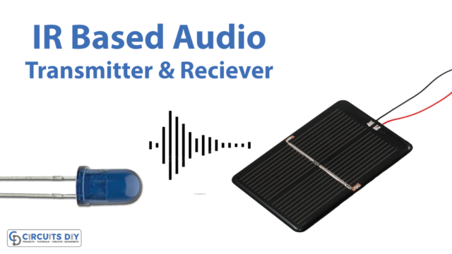 Simple IR Audio Transmitter & Receiver Using Solar Cells
 Heart Rate Monitor Circuit Using LM358 IC | DIY Project
 5 Volt USB Mobile / Car Charger using LM7805 - DIY Project


