
Much of the power supply in the present day is quite reliable because of technical advances and better design preferences due to defective manufacturing or the main switching transistor or the MOSFET going bad. It may also fail due to the input’s overvoltage, while protective devices such as Metal Oxide Varistor (MOVs), but the device is useless if a MOV triggers.
To solve this problem, we can build an op-amp over a protective device that can detect high voltages and cut in a fraction of second input power, protecting the system from high voltage surges.
Hardware Component
The following components are required to make Over Voltage Protection Circuit
| S.no | Component | Value | Qty |
|---|---|---|---|
| 1. | IC | LM358 | 1 |
| 2. | Transistor | BD139 | 1 |
| 3. | Screw Terminal | 5mm | 6 |
| 4. | Diode | 1N4007 | 9 |
| 5. | Capacitor | 0.1uF | 2 |
| 6. | Resistor | 56K, 1W, 1.5K, 1K, 1M, 560K, 62K | 2, 1, 2, 1, 2, 1 |
| 7. | Potentiometer | 10k | |
| 8. | PCB Relay SRD | 12VDC-SL-C | 1 |
| 9. | Voltage Regulator | LM7805 | 1 |
| 10. | LED | – | 1 |
| 11. | Clad Board | Generic 50x 50mm | 1 |
LM358 Pinout
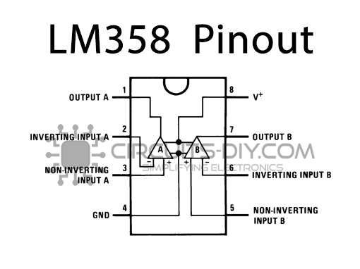
For a detailed description of pinout, dimension features, and specifications download the datasheet of LM358
LM7805 Pinout

For a detailed description of pinout, dimension features, and specifications download the datasheet of LM7805
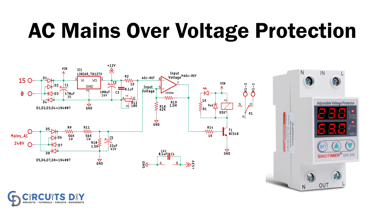
Over Voltage Protection Circuit
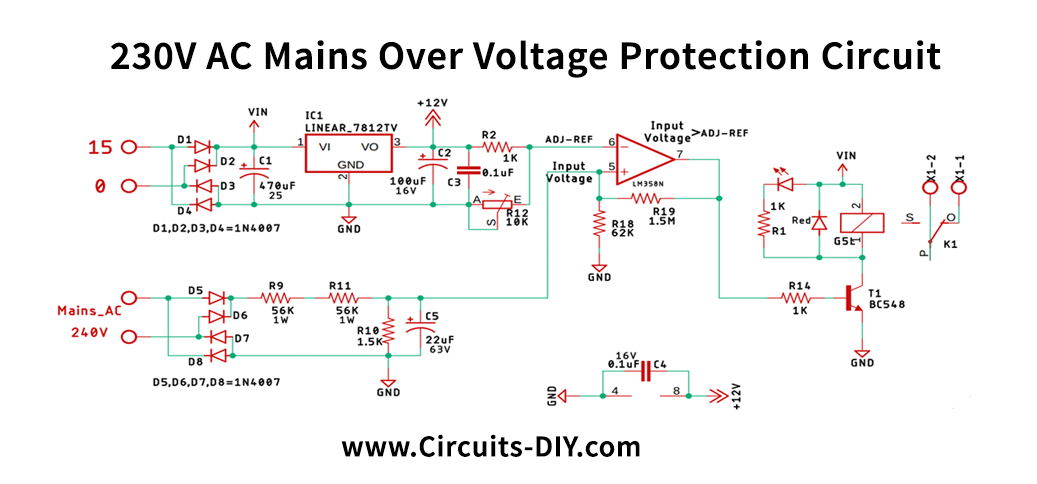
Circuit Operation
Let’s take the circuit apart to understand the fundamental operating principle of each part of the circuit’s fundamental operating principle to understand the basic working principle.,
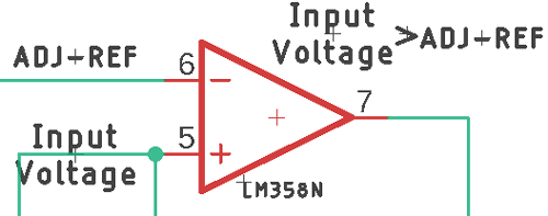
The OP-Amp is configured as a comparator at the heart of this circuit. We have a basic LM358 op-amp in the scheme, and its pin-6, our reference voltage generated by an LM7812 voltage regulator IC. On pin-5, our input voltage is created by the main supply voltage. If the input voltage surpasses the reference voltage, the op amp’s output is higher, and we can operate a transistor with a high signal that turns on a relay. Still, the circuit is in a serious problem because of the noise in the input signal.
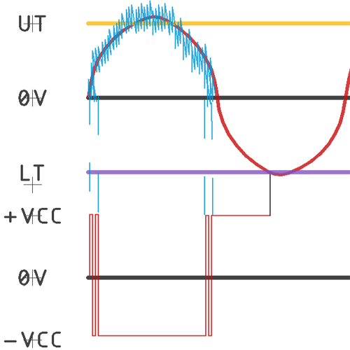
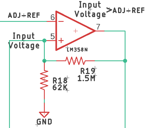
The solution is to add Schmitt’s hysteresis to the input trigger. If the op-amp is configured with positive feedback, we will expand the input margin according to our needs. We’ve provided feedback using R18 & R19, as you can see in this image, by adding two threshold voltages, one being the upper threshold voltage, the other the lower threshold voltage.
Calculating the Component Values for Over Voltage Protection
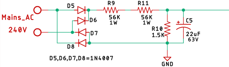
If we look at the diagram, our main input is rectified using a bridge rectifier. The voltage divider is created with R9, R11, and R10, and then we filter the input using a capacitor 22uF 63V.
After the divider calculation, we can get a voltage output of 3.17V, and now we would calculate the upper and lower voltages of the threshold; let’s say we want to cut power when the input voltage reaches 270V. If we calculate the voltage divider again, we have an output voltage of 3,56V, our upper threshold. Our lower threshold stands at 3.17V, while the Op-amp is grounded.
Now we can conveniently calculate the upper and the lower threshold voltages using a simple voltage divider formula. The calculation is seen below, using the schematic as a reference,
UT = R18 / (R18+R19) * Vout = 62K / (1.5M + 62K) = 0.47V
LT = R18 / (R18+R19) * -Vout = 62K / (1.5M + 62K) = 0V
After the calculation, we can see that we set your upper threshold voltage at 0.47 V above the trigger level with the help of positive feedback.
Note: Please note that our practical values can distinguish a little bit from our calculated values because of the tolerances of resistors.
Applications and Uses
This circuit provides the transformer with a 230V power supply and supplies the power to the rectifier circuit as the input. The transformer’s output is often fed into the board, giving the power and the reference voltage to the circuit.
Related posts:
 Obstacle Detector by IR Sensor & ATmega328 Arduino
 Non-Contact AC Voltage Sensor Using LM358
 How to make Short Circuit Protector | Power Supply Protector
 Electronic Appliances Switch Left open Indicator
 Heart Rate Pulse Sensor - BPM Meter using OLED & ESP32
 12V Relay-based Timer Switch Circuit Using BC547 Transistor


