With the constant growth of the process control industry, the need and applications for On/Off delay timers is ever increasing. There are many industrial processes and tasks that would not be possible without the application of Relay based Timer Switches.
A Relay based Timer timer switch is a process control device that starts or ends a process with respect to the preset time defined by the RC time constant of the circuit. It is generally used in controlling commercial or industrial-grade equipment such as HVAC equipment, traffic lighting, and large pumps. In today’s tutorial, we will design a 12V Relay based Timer Switch Circuit Using a BC547 Transistor & a small number of other components.
BC547 Transistor
The heart of this 12V Relay based Timer Switch is a BC547 NPN switching transistor. BC547 is one of the most common switching transistors for low to medium-voltage switching applications. It is an NPN transistor, meaning that the IC collector and emitter will be left open during reverse bias operation and during the forward bias, the base pin will be held at the ground and will be closed when a signal is provided to the base pin.
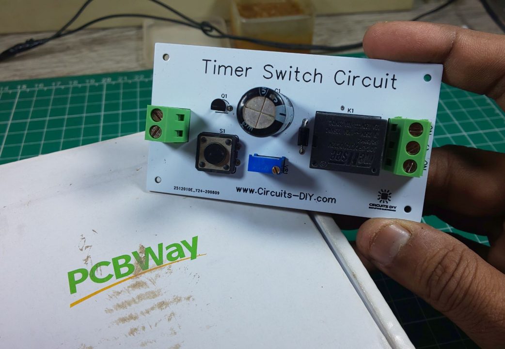
PCBWay commits to meeting the needs of its customers from different industries in terms of quality, delivery, cost-effectiveness, and any other demanding requests. As one of the most experienced PCB manufacturers in China. They pride themselves to be your best business partners as well as good friends in every aspect of your PCB needs.
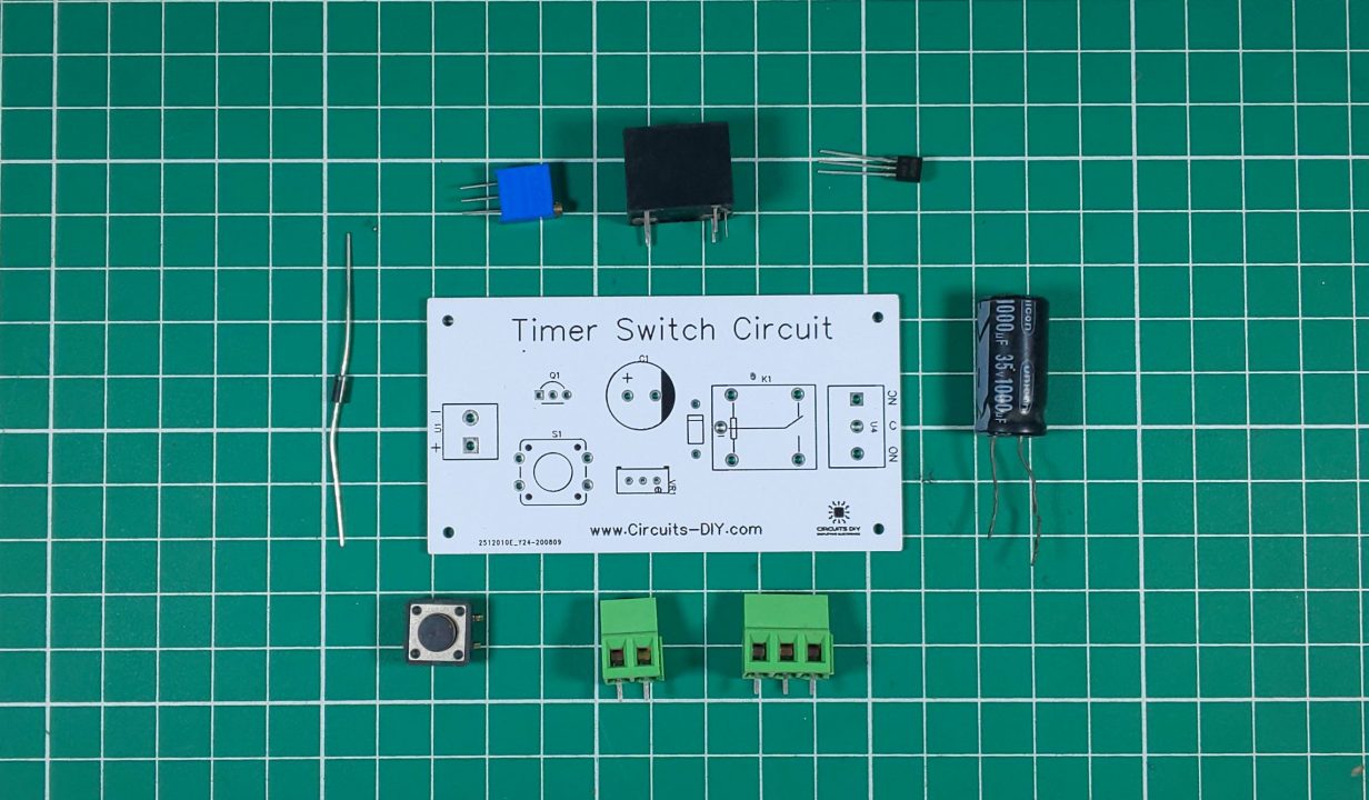
Hardware Components
The following components are required to make Timer Switch Circuit
| S.no | Component | Value | Qty |
|---|---|---|---|
| 1. | Relay | SPDT/5V | 1 |
| 2. | AC – DC Converter | 220V/12V | 1 |
| 3. | Transistor | BC547 | 1 |
| 3. | Block Connector | – | 1 |
| 4. | Potentiometer | 10K | 1 |
| 5. | PushButton | – | 1 |
| 6. | Capacitor | 1000uF | 1 |
| 7. | Diode | 1N4007 | 1 |
| 8. | Wall outlet with Plug | 220V | 1 |
| 9. | Soldering Iron | 45W – 65W | 1 |
| 10. | Soldering Wire with Flux | – | 1 |
| 11. | Veroboard | – | 1 |
| 12. | Jumper wires | – | As per need |
BC547 Pinout

For a detailed description of pinout, dimension features, and specifications download the datasheet of BC547
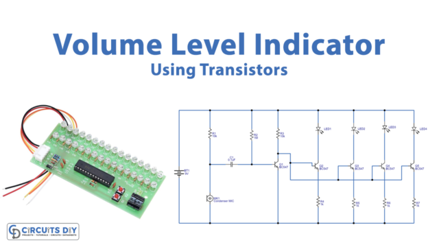
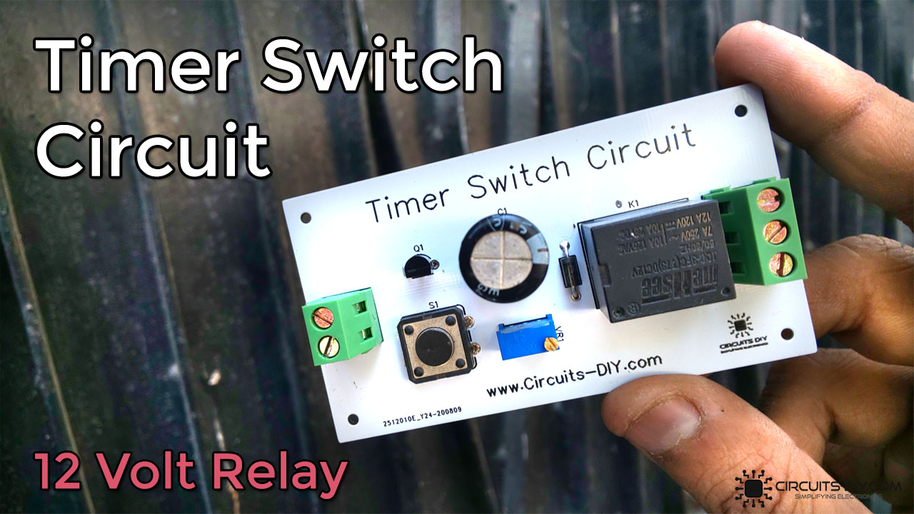
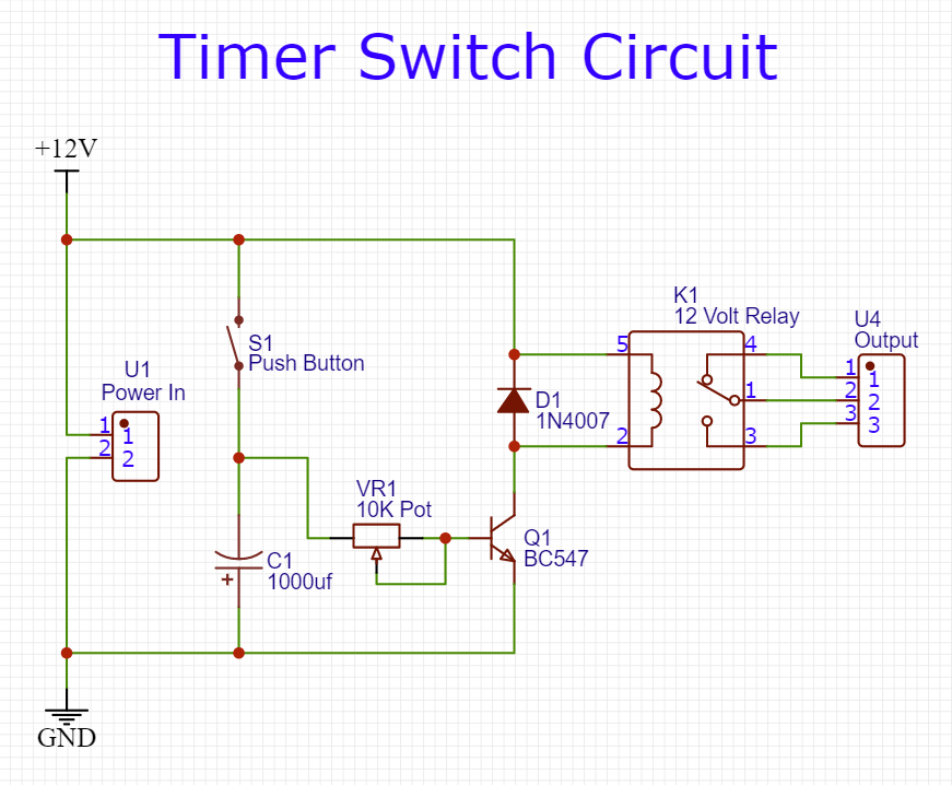
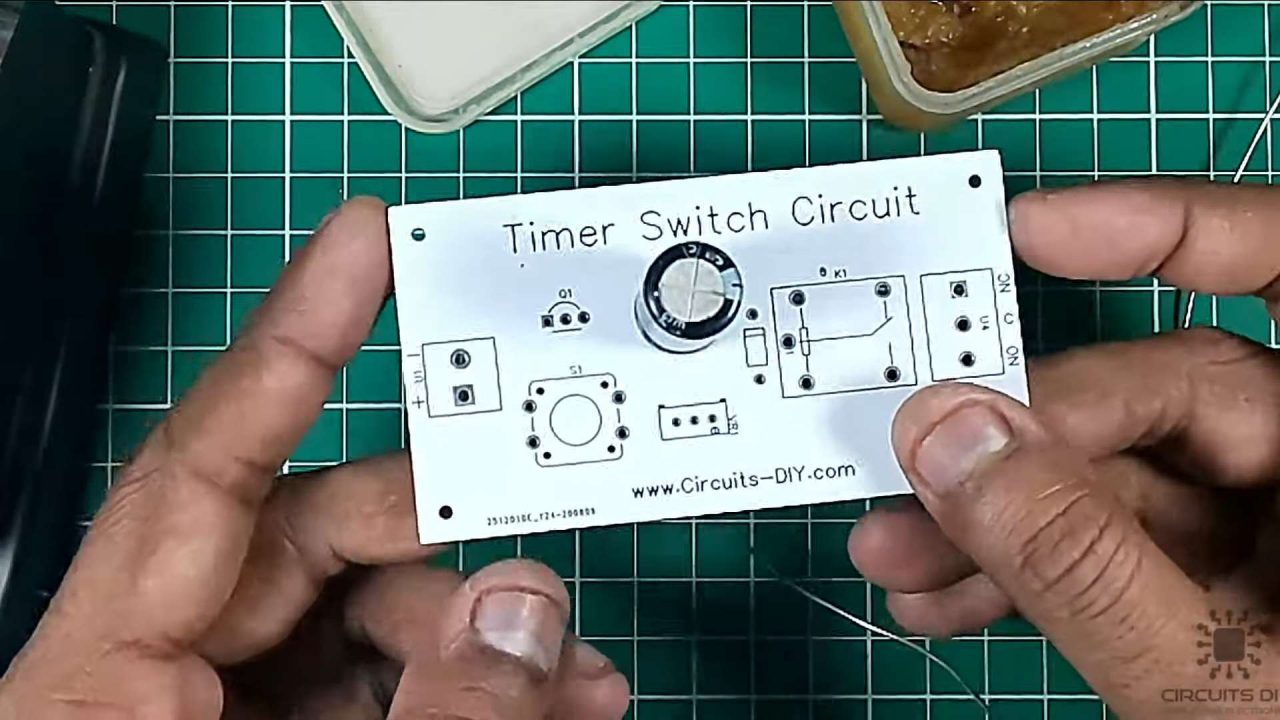
Timer Switch Circuit
Useful Steps
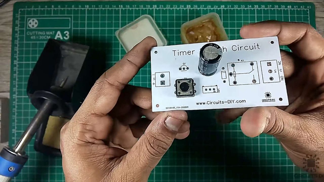
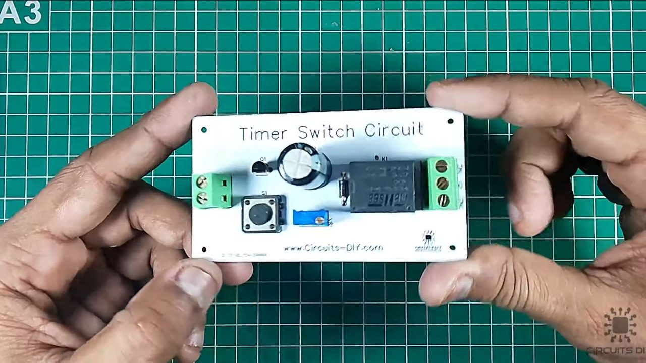
1) Solder the 1000uF capacitor on the PCB board.
2) After that, solder the pushbutton on the PCB board.
3) Solder the BC547 NPN transistor on the PCB board.
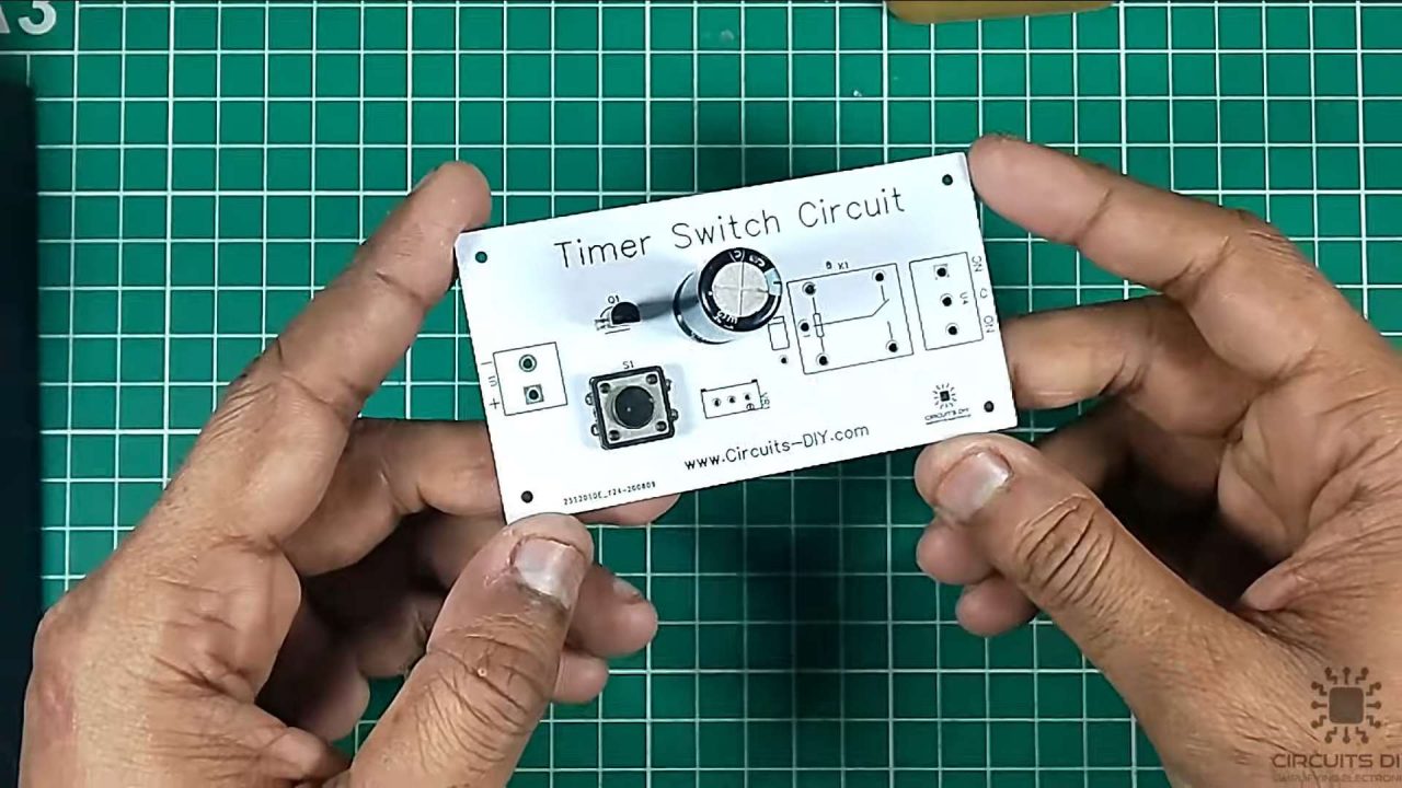
4) After that, solder the 10K pot on the PCB board.

5) Solder the 1N4007 diode on the PCB board.

6) After that, solder the 5V SPDT relay on the PCB board.

7) Solder the input and output terminal block connector on the PCB board.
8) After that, connect the battery clip with the input terminal block connector.
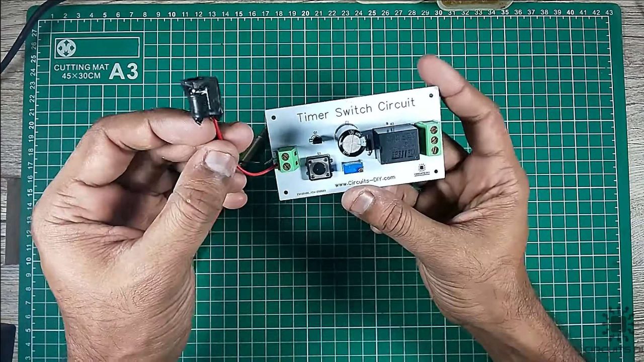
9) Tune the 10K pot to your desired preset value.

10) Power up and test the circuit using a 9V battery.
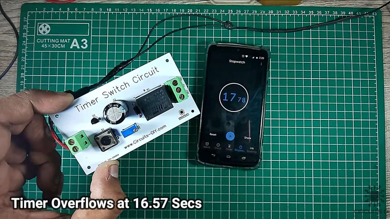
Working Explanation
The working of this circuit is actually pretty simple. Here, a 10K pot sets the preset resistance for the timer circuit. . On powering on the circuit and pressing the pushbutton, the 1000uF capacitor charges & discharges as per the resistive preset delay introduced by the 10K preset pot.
The output from the 10K pot functions as a control signal on the base of the BC547 transistor. Here, we are using a flyback diode (1N4007) to protect the relay against any undesirable feedback due to shorts. The collector output from the transistor energizes the coil terminal of the 5V relay. This makes the relay and powers up any external circuit that is connected between the NC and COM terminal of the relay. Always choose a relay that electrically conforms with the input supply voltage and the output load connected to it.
Application
- This circuit plays an important role in controlling many process control tasks such as automated control of AC and DC drives, sectionizing and criminalizing factory operations, etc.