
In this tutorial, we will make a “1 Watt Amplifier Circuit”. The power amplifiers amplify the power level of the signal. This amplification is done in the last stage of audio applications. After the audio signal is converted into an electrical signal, it has several voltage amplifications. After which the power amplification of the amplified signal is done just before the loudspeaker stage. As we know that for a compact hand-held device, making an audio amplifier with low voltage consumption is a difficult job.
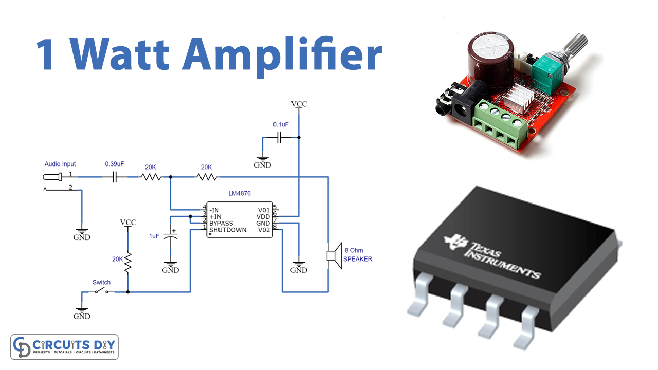
Here we design a 1-watt audio amplifier circuit with IC LM4876 from texas instruments, it is a 1.1-watt audio power amplifier IC with the logic low shutdown. This IC does not require output coupling capacitors, bootstrap capacitors, or snubber networks. It is perfectly suited for low-power portable systems. It can provide 1-Watt continuous average output power into an 8Ω speaker and operate with 2.0V to 5.5V with low current consumption.
Hardware Required
| S.no | Component | Value | Qty |
|---|---|---|---|
| 1. | IC | LM4876 | 1 |
| 2. | Resistor | 20KΩ | 3 |
| 3. | Capacitor | 0.39μF,1μF,0.1μF | 1,1,1 |
| 4 | Switch | – | 1 |
| 5. | Connecting Wires | – | – |
| 6. | Speaker | – | 1 |
| 7. | Power Supply | 5.5V | 1 |
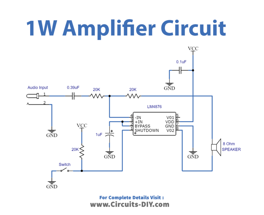
Circuit Diagram
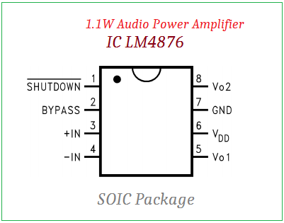
Pin Configuration of LM4876 IC
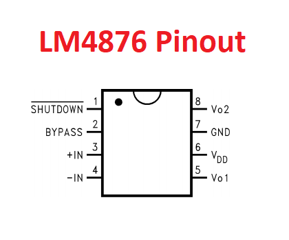
LM4876 boomer IC is a single 5V supply bridge-connected audio power amplifier. This IC is capable of delivering 1.1W of continuous average power to an 8Ω load with 0.5%, available in 10-pin VSSOP and 8-pin SOIC packages. It does not require an output coupling capacitor. It has a unity-gain stable, external gain set, and a shutdown current of 0.01µA. This IC is designed specifically to provide high-quality output power with a minimal number of external components. It has a supply voltage range of 2.0 V to 5.5 V.
Working Explanation
The main part of this amplifier circuit is the LM4876 boomer IC. This IC is an 8-pin SOIC package, that requires few passive components to operate. Here the whole amplifier circuit design occupies a minimum area. First, connect the audio input to the -IN pin through input capacitor C1 and Input Resistor R1. Then connect feedback resistor R2 between the -IN pin and V01 pin. And the shutdown pin is connected with pullup resistor R3 and switch, it is an active low pin. The LM4876 has two internal operational amplifier circuits, these are connected in a closed loop with the help of external feedback resistors. These two internal operational amplifiers will give a 180º phase difference (Amp1 output serves as the Amp2 input. This results in both amplifiers producing signals identical in magnitude, but 180° out of phase. Taking advantage of this phase difference, a load is placed between V01 and V02 and driven differentially (commonly referred to as bridge mode). Hence the load is connected in bridge mode. Finally, the 8Ω output speaker (load) is connected between the V01 and V02 pins in bridge mode. Another advantage of the differential bridge output is no net DC voltage across the load.
Applications
Can be used in portable electronic devices and low-voltage audio systems.


