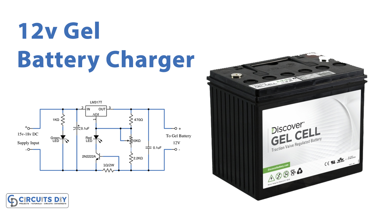
In this tutorial, we are going to make a “12 Volt Gel cell Battery Charger Circuit”.
To charge batteries, we need to put a voltage across the terminals, and the battery starts charging. The charging protocol depends on the size and type of the battery being charged. Some battery types have a high tolerance for overcharging and can be recharged by connection to a constant voltage source or a constant current source, depending on the battery type. If safe charging, fast charging, and/or maximum battery life are important, that’s when things get complicated. A widely used battery is a gel cell battery because it has easy maintenance and is cheap. But as we need a suitable battery charger circuit for longer service life.
Here we design a simple 12-volt gel cell battery charger circuit by using a few easily available components. This circuit can charge a gel cell battery with reverse current and overcharging protection. We know a Gel cell battery is a VRLA (valve-regulated lead-acid) battery with a qualified electrolyte, and these types of batteries are maintenance-free batteries.
Hardware Components
The following components are required to make Gel Battery Charger Circuit
| S.no | Component | Value | Qty |
|---|---|---|---|
| 1. | Voltage Regulator IC | LM317 | 1 |
| 2. | Transistor | 2N2222A | 1 |
| 3. | Resistors | 1KΩ, 470Ω, 2.2KΩ, 1Ω/2W | 1,1,1,1 |
| 4. | Variable Resistor | 10KΩ | 1 |
| 5. | LED | – | 1 |
| 6. | Capacitors | 0.1µF | 2 |
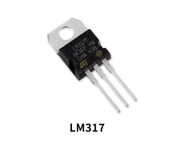
LM317 Pinout
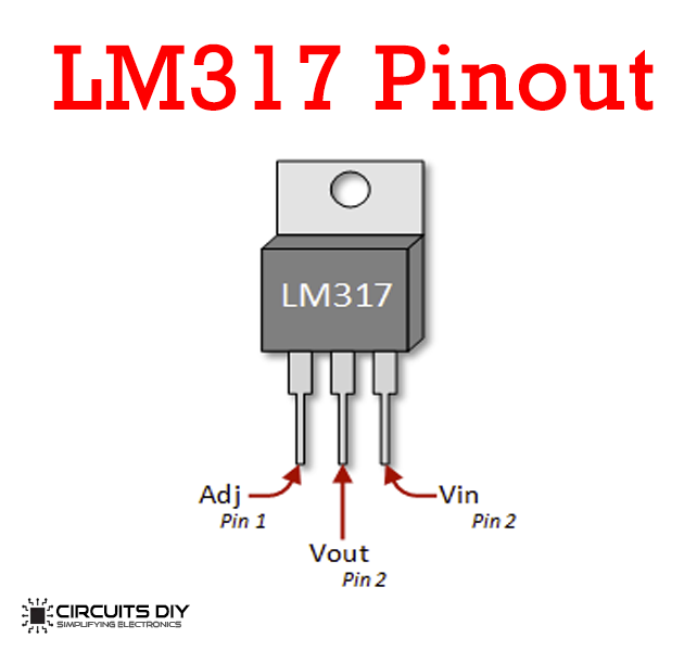
For a detailed description of pinout, dimension features, and specifications download the datasheet of LM317
2N2222A Pinout
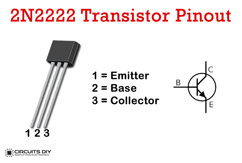
For a detailed description of pinout, dimension features, and specifications download the datasheet of 2N2222A
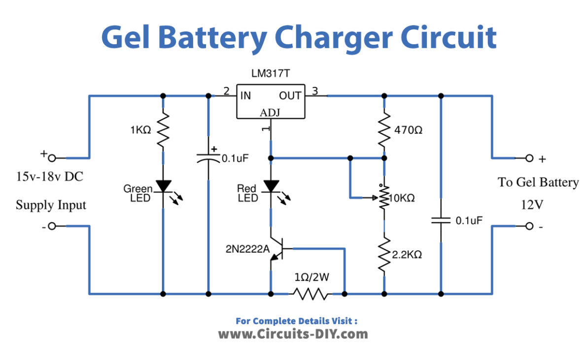
Gel Battery Charger Circuit
Working Explanation
This 12 Volt Gel cell Battery Charger Circuit utilizes a 15 Volt to 18 Volt DC input supply and provides a regulated 12 Volt DC supply to the charging Battery. This circuit is designed with an adjustable charging current and indicator LED. This charger circuit is designed to meet the requirements of Gel cell batteries and this circuit capable of charging a 12 Volt battery. The main part of this circuit is the positive adjustable voltage regulator, we use an LM317 IC as a 1.5A adjustable positive voltage regulator. It converts the input DC voltage into stable voltage to charge the battery. Which we adjust the 10K potentiometer-VR1 for 12V output. IC LM317 and use a heat sink for this IC. Place transistor 2N2222A between Adj pin of regulator and ground supply base terminal and emitter terminals are separated by the resistor R2 and this transistor helps to maintain constant current at the output. We set the output current by the current sensing resistor(R2) in the ground or (–) terminal. The R2 is currently limiting. Resistors R3, RV1, and R4 are connected serially between output bias and the variable resistor terminal is connected with the Adj pin of the regulator.
Here Red LED indicates the charging current. Input supply for this circuit can be 15 to 18 Volt DC supply and use proper Step-down transformer and bridge rectifier for input supply, at the end this circuit will provide 12V DC with the adjustable current. Place the Gel Cell battery at the end with proper polarity. When the current flows through R2. This results in a voltage across the base and emitter of transistor-Q1. It is forward-biased. Thus, Q1 conducts current to LED1 and adj of IC1.
The red LED1 will show a battery charge status. When the battery voltage reaches the selected point, the current will drop to a few milliamps. And it makes the voltage across Q1 and LED1 lower. When its current drops about 5%, the LED turns off, and the current drops to almost zero. When we finish the circuit and checked everything already connect the 12V battery to the output. The voltage level will drop. When measuring the current flowing through the battery initially it is approximately 600mA. When the voltage level starts to rise, close to 12V. The current through the battery will also be less, it shows that the battery is fully charged because the voltage level is exactly 12V. It takes about 9.5 hours.
Applications
Can be used in most handheld electronic devices.