Introduction
You may have seen that heavy and expensive transformers are part of many applications. These transformers cost a lot and we as humans always work to make things at cheaper costs. So, to replace those heavy transformers, a voltage doubler can take its place. The voltage doubler is the circuit that not only converts the AC voltage into DC but also doubles its output DC voltage. And, therefore it has some major advantages. For example, it can strengthen the voltage multiplication factors if cascaded with multipliers. So, now, in this tutorial, we are going to discuss the “12V to 24V Voltage Doubler”
Voltage doublers also have types. It includes a half-wave voltage doubler and a full-wave voltage doubler. And full-wave doubler has more advantages as it is easier to ripple high-frequency ripples because its output frequency is twice the supply frequency.
Hardware Required
| S.no | Component | Value | Qty |
|---|---|---|---|
| 1. | Step-down Transformer | 230V AC to 12V AC / 1 Amps | 1 |
| 2. | Diode | 1N4007 | 1 |
| 3. | Capacitor | 2200µF, 4700µF | 2,1 |
| 4. | DC Supply | 24V |
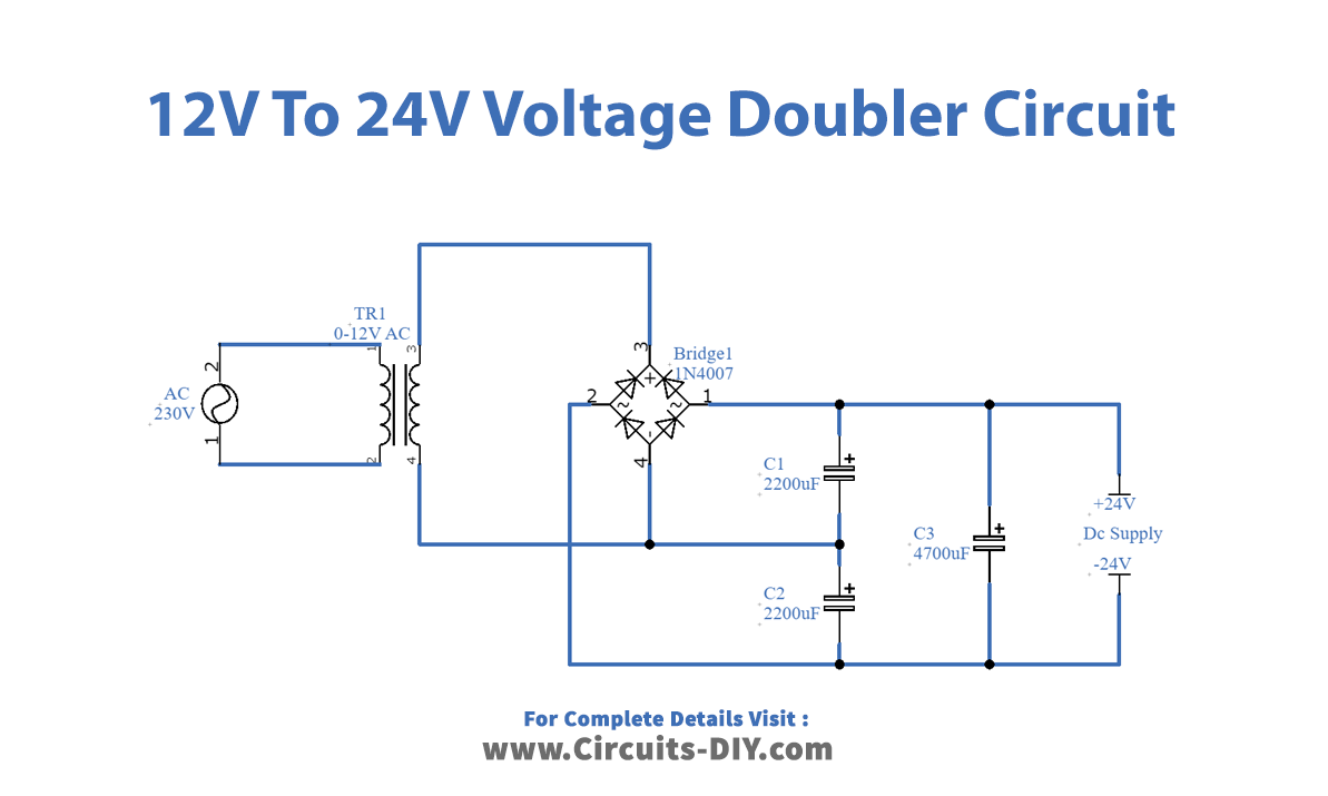
Circuit Diagram
Working Explanation
The 12V to 24V Voltage Doubler first uses the transformer that converts the 230V of AC into 12V of DC voltage. Now this DC voltage needs to be converted onto 24V (that is double 12V). So, first, there is a rectifier circuit to rectify the voltage. There are three capacitors in the circuit. The capacitors C1 and C2 charge during the positive and negative cycles. And during the DC supply both of these capacitors discharge and capacitor C3 charges, Hence the output comes in double the supply voltage.
Application and Uses
- This circuit can replace heavy transformers for different applications
- Copy machines can employ this circuit.
- We can also use it in television CRT circuits.
- And in many other applications like radar equipment, X-ray systems, etc