Introduction to Power Amplifier
A circuit that increases the level of its input power to drive the different loads is known as the Power Amplifier Circuit. Certainly, it’s an electronic circuit that is designed to boost the magnitude of the input signal. The power amplifier not only delivers a great amount of power at the output but also handles a large amount of current in the circuit. So, this article is about making a power amplifier using IC BA5417. Therefore, before making the amplifier we need to understand the function of an IC.
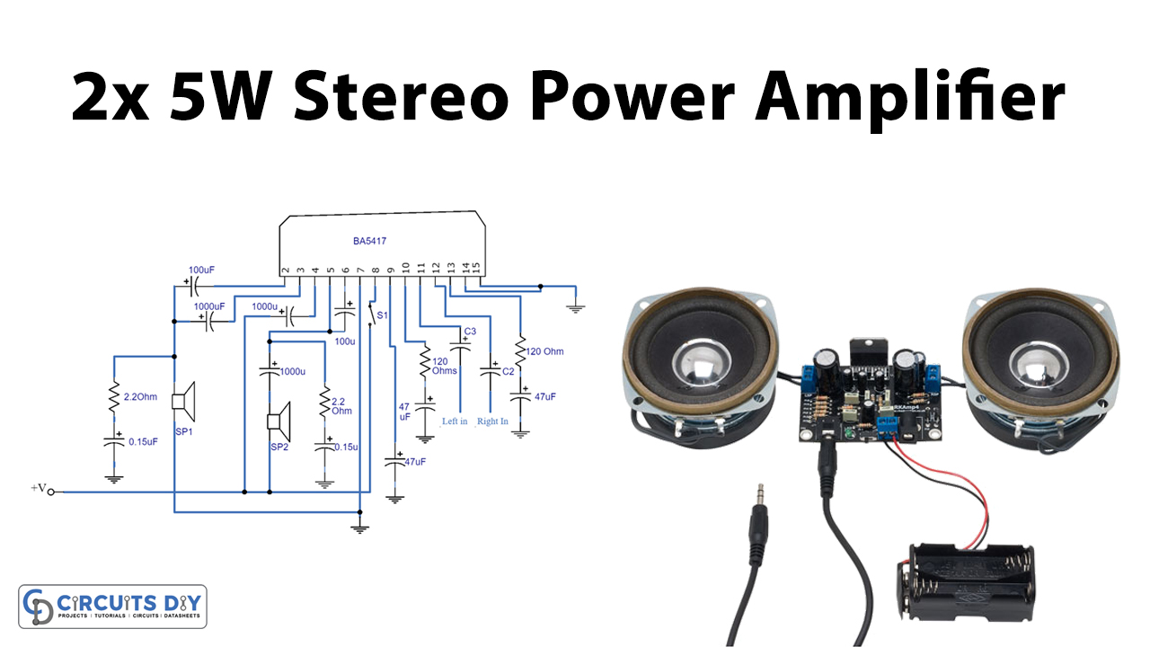
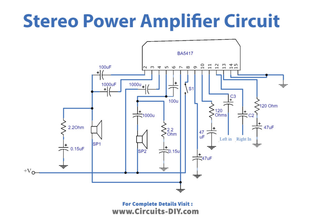
BA5417 is a monolithic dual-power IC with built-in two high-output speakers. And, 2×5 watt can be generated when Vcc is equal to 12 V and load resistance is almost 3 ohms. Also, it dissipates the high power. Thus, requires heat sinks. The IC has a circuit that prevents ripple addition. Hence, used in audio systems, LCD TVs, etc.

Hardware Components
The following components are required to make the Power Amplifier Circuit
| S.no | Component | Value | Qty |
|---|---|---|---|
| 1. | Vero Board/ PCB Board | – | 1 |
| 2. | Electrolytic Capacitor | 0.1uf, 47uf, 100uf, 1000uf, DC decoupling cap | 2, 2, 3, 3, 2 |
| 3. | Resistor | 2.2ohms, 120ohms | 2, 2 |
| 4. | Speakers | – | 2 |
| 5. | SPST Switch | – | 1 |
| 6. | IC | BA5417 | 1 |
| 7. | Supply Voltage | 12V | 1 |
BA5417 Pinout
For a detailed description of pinout, dimension features, and specifications download the datasheet of BA5417
Power Amplifier Circuit
Working Explanation
The circuit has capacitors C2 and C6 as coupling capacitor that amplifies output and gives it to their respective speakers. The capacitors C10 and C11 are decoupling capacitors that block DC levels in the input signals. While C1 and C5 are bootstrap capacitors that are connected to the output of the amplifier. And, provides bias voltage that exceeds the supply voltage.
Application and Uses
- Audio systems
- Broadcast transmitters
- Televisions
- Wireless transmitters
- Stereo radio cassette players