Nowadays, Analog electronics have generally become the backbone of amplifiers. They are generally used in the electronics sector. Although, almost all audio-related system includes amplifiers.
Furthermore, a sound electronics section is the power amplifier. It is however done to enhance the power of the input signal. The operational amplifier increases the signal voltage levels in sound electronics but is not able to deliver the current wanted to shift a voltage. Moreover, we will design a 10W amplifier in this tutorial with an 8 Ohm impedance speaker connected to it. We are now, therefore, aiming to provide the 10 Watt output over its output Load to use an OPA and two additional power transistors.
Hardware Component
The following components are required to make 10 Watt Audio Amplifier Circuit
| S.no | Component | Value | Qty |
|---|---|---|---|
| 1. | IC with eight-pin IC Base | LF351 | 1 |
| 2. | Transistor | TIP122, TIP127 | 1,1 |
| 3. | Capacitor | 0.82uF, 10pF, 1pF | 1,1,1 |
| 4. | Resistor | 200R, 3.2k, 4.7k, 47k | 2,1,2,1 |
| 5. | Speaker | 8 Ohms 10 Watt | 1 |
| 6. | Rail to the Rail power supply | +12V GND -12V | 1 |
| 7. | Vero board (dotted or connected anyone can be used) | – | 1 |
| 8. | Solder wire and Soldering Iron | – | 1 |
| 9. | Nipper and Wire stripper tool | – | 1 |
| 10. | Wires | – | 1 |
| 11. | Aluminum heat sink | – | 1 |
LF351 Pinout
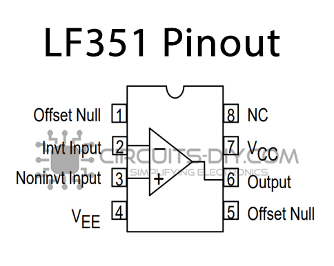
For a detailed description of pinout, dimension features, and specifications download the datasheet of LF351
TIP127 Pinout
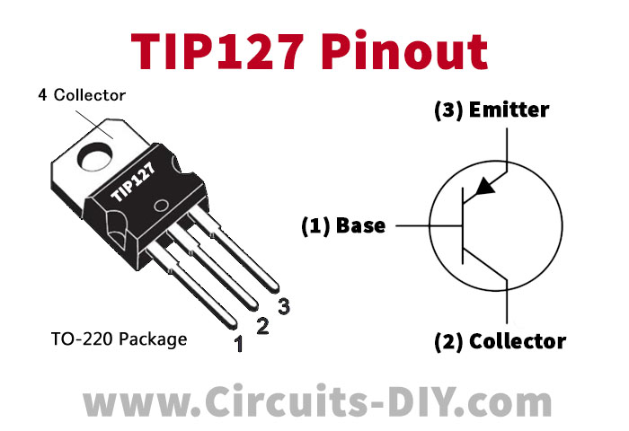
For a detailed description of pinout, dimension features, and specifications download the datasheet of TIP127
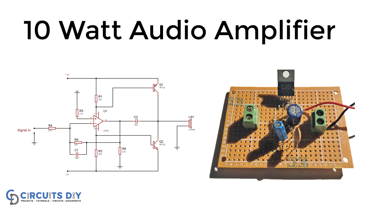
10 Watt Audio Amplifier Circuit
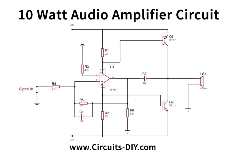
Circuit Operation
Meanwhile, the schematic for the 10-watt amplifier is really quite simple. Generally, the LF351 amplifies signal voltage and provides the necessary power amplification with two power transistors. The power is however taken directly from the power supply and produced by two transistors to the 8 Ohms Loud Speaker. Hence, as Sinusoidal waves change polarity, TIP127 provides a positive peak power amplifier, and TIP 122 gives a negative peak signal power amplification.
Additionally, the two main components are TIP122 and TIP 127. Therefore, these two transistors are very much like 100V Sustaining Voltage Collector-Emitter @ 100 mA. Thus, the current high DC gain in both ICs is typically hFE=2500.
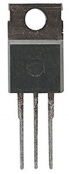
The TO-220B package is subsequently highlighted in the above picture, both transistors packages. Meanwhile, for an excellent heat transfer and beneficial for the modification of a heatsink, this kit is necessary. These transistors are henceforth partly influenced by the 200R resistors. Thus, the amplified voltage is determined from the TIP122 and TIP127 collector junctions.
Applications and Uses
The preamplifier here is Op-amp IC TL081. In fact, an opamp can be used instead of TL081 with matching supply scores.