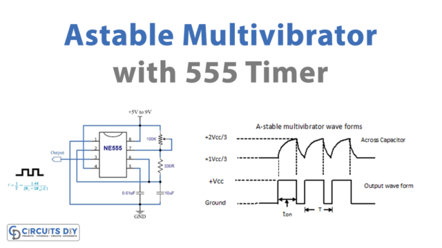
In this circuit, we are making a 555 Universal Automatic Battery Charger. Any type of rechargeable battery having voltages ranging from 6 to 24V can be charged with this circuit. The output current of this circuit is 10A max.
This circuit can also be modified to charge batteries having lower voltages than 6V. For that, you will have to change the value of the Zener diode to 2.4-2.5V. Select a power supply with at least 1.5V to 3V above the voltage of the battery undercharge. And the current of the power supply should be selected according to the 1/10 of the battery AH. If you want to charge a 6V 10 AH battery then use a 7.5V DC and 1A current power supply.
Hardware Components
| S.no | Component | Value | Qty |
|---|---|---|---|
| 1. | Battery | – | 1 |
| 2. | IC | NE555 Timer | 1 |
| 3. | Phototransistor | PC817 | 1 |
| 4. | Transistor | 2N3906 | 1 |
| 5. | Relay | – | 1 |
| 6. | Diode | 1N4148 | 3 |
| 7. | Zener diode | 3.3V | 1 |
| 8. | Resistor | 1KΩ, 10KΩ, 8.2KΩ, 470RΩ, 100KRΩ | 2, 1, 1, 1, 1 |
| 9. | Capacitor | 10nF | 1 |
| 10. | LED | – | 1 |
| 11. | Switch | – | 1 |
| 12. | Power Supply | – | 1 |
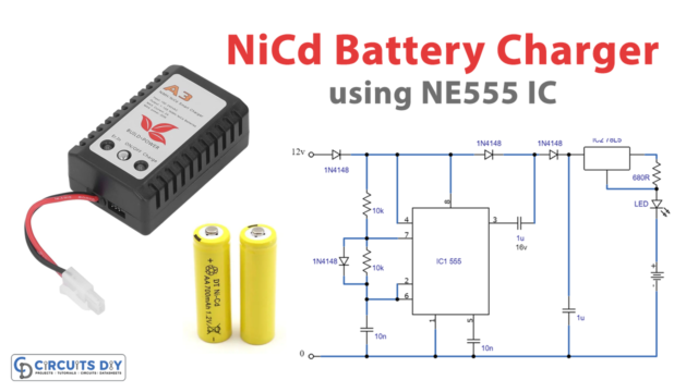
Circuit Diagram
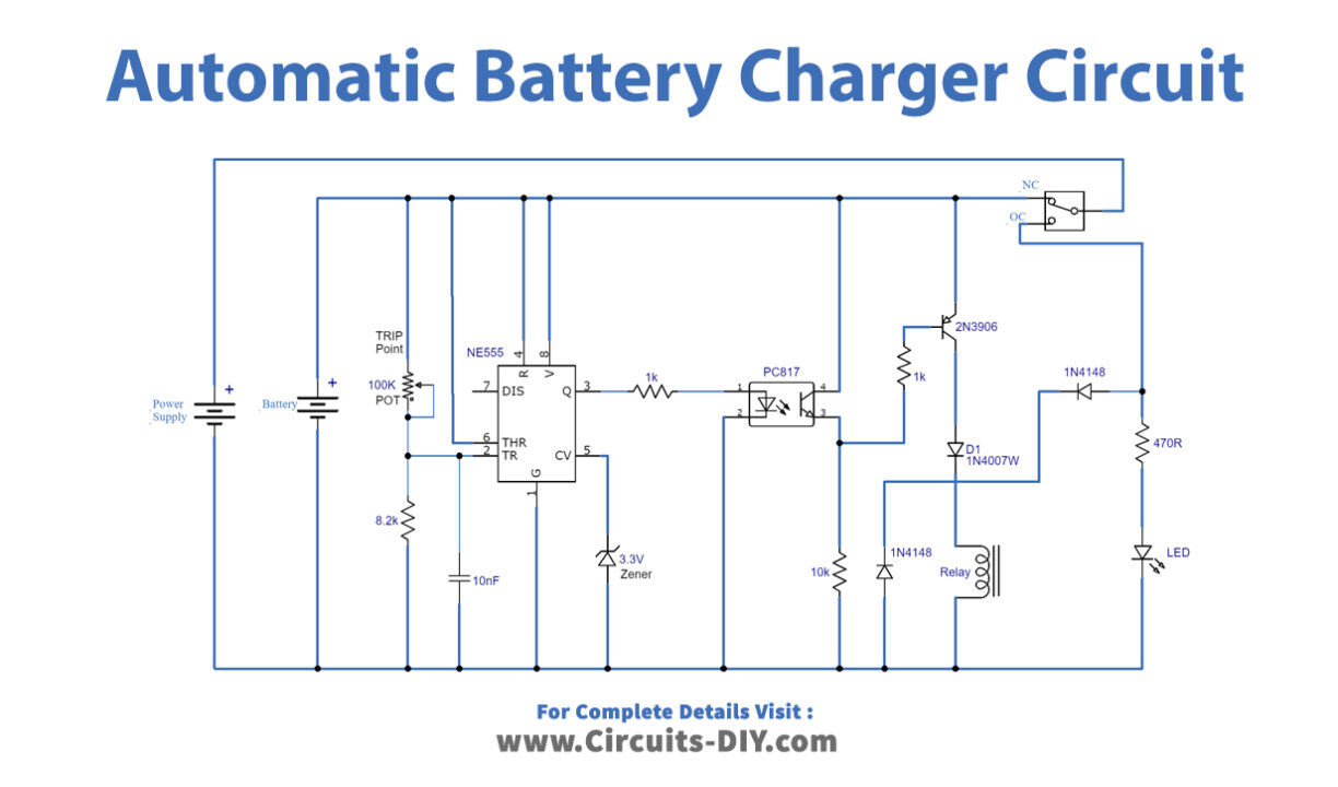
Working Explanation
We are using a 555 timer IC which is wired as a comparator to detect the voltage of the battery. A 100K variable resistor is used to set the trip point. The trip point will set the point of voltage at which you want your battery to stop charging and get disconnected from the circuit.
The trip point should be set according to the battery type, a 6V battery shows 7.2V on a DMM when it is fully charged, with the power supply connected. So the trip point set for a 6V battery should be 7.2V.
Circuit Adjustments
- Take an adjustable power supply and set the voltage to 14.4V if you are using a 12V because when a 12V gets fully charged it shows 14.4V on DMM.
- Remove the power supply and the battery attached to the circuit and place this adjustable power supply in the place of the battery.
- Adjust the adjustable resistor until the LED lights up.
- Remove the adjustable power supply to connect the actual power supply and the battery in the circuit.
- Now when the battery gets fully charged it will disconnect from the supply automatically and the LED will turn on.
- The same procedure will be followed for batteries with other voltages. The voltage in the adjustable power supply will be set according to the battery’s voltage shown in DMM when fully charged.