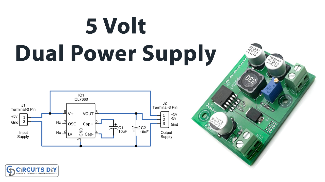
In this tutorial, we are going to make a “5v Dual Power Supply Circuit”.
The objective of this project is to convert 220V AC supply into +5V and -5v DC supply, as we get positive and negative 5v power supply at the same time that is why it is named Dual Power Supply. Most of Analog Electronic circuits require dual power supply rails for proper balanced operation, and many Controllers or output actuators need both positive and negative supplies with Ground. Especially we need this type of circuit when we are designing Operational amplifier circuits.
As we cannot provide those biases to circuit elements by using a power source or USB power source. Here we designed a simple 5v Dual Power Supply Circuit by using ICL7660. IC L7660 is a monolithic, CMOS switched-capacitor voltage converter that inverts, doubles, divides, or multiplies a positive input voltage. It operates with only two external capacitors and is capable of converting voltage from 1.5 V to 10 V, with no external diode over the full temperature range.
Hardware Component
The following components are required to make a Dual Power Supply Circuit
| S.no | Component | Value | Qty |
|---|---|---|---|
| 1. | IC | L7660 | 1 |
| 2. | Capacitor | 10µF/16V | 2 |
| 3. | Screw Terminal | 2 Connector | 1 |
| 4. | Screw Terminal | 3 Connector | 1 |
| 5. | Connecting Wires | – | – |
| 6. | Power Supply | 5V | 1 |
L7660 Pinout
For a detailed description of pinout, dimension features, and specifications download the datasheet of L7660
Dual Power Supply Circuit

Working Explanation
The Circuit is made by around ICL7660 (U1) along with two capacitors C1 and C2. The input voltage of +5V can be obtained from any USB port of a laptop/computer or a charger/adapter, 5V output from the source is given to pin 8 of U1. IC L7660 contains a linear regulator, an RC oscillator, a voltage level translator, and four power MOS switches internally. To ensure latch-up-free operation, the circuitry automatically senses the most negative voltage in the device and ensures that the N-channel switch source-substrate junctions are not forward biased.
The oscillator frequency runs at a nominal 10 kHz (for VCC = 5 V), but that frequency can be decreased by adding an external capacitor to the oscillator (OSC) terminal or increased by overdriving OSC with an external clock.
The IC U1 and capacitors (C1 and C2) form the voltage inverter section that converts +5V to -5V. The Converted -5V supply is available at pin 5 of U1. Thus, the dual power 5V supply is available at the connector J2.
Applications
- We use a dual power supply In Audio amplifiers, operational amplifiers, and power amplifiers.
- For low voltage DC motor direction control, we can use this dual power supply circuit.
- In a cell phone charging circuit.
- In a power bank circuit.