Have you ever thought to make any appliance that accords with your wish? For instance, a robot that you can control, an automation device that you can manage at your fingertips, a weather station that can give you quick updates about the weather game player, etc. Is it not thrilling to think about? Does this not interesting enough to learn about?
So, If you’re a beginner at learning electronic circuits, or a student of electronic engineering then you must have heard the term “microcontroller”. But, they puzzled you about this term, right? Does this make you confused about learning electronics? Do you feel some sort of trouble where to understand these whole microcontroller things? Are you getting frustrated that you don’t even know the basics of this small microcontroller? So, Let’s first understand this term called a microcontroller.
What are the microcontrollers? The term microcontrollers are for those integrated circuits (ICs) that are basically the minicomputers, that can run small software programs, process, and runs the data faster than humans can even imagine or think. And, there are many kinds of microcontrollers available, some are new, some are old. Some have less memory, some have greater memory, Some work faster, and some work slower. Some have only a few applications and some have wider applications. These microcontrollers include PIC, AVR, ESP, 8051, etc. Hence the primary focus of this article is the 8051 microcontroller. So, don’t worry, folks. And read this article further, to learn a whole beginner guide about this small microcontroller board called Arduino.
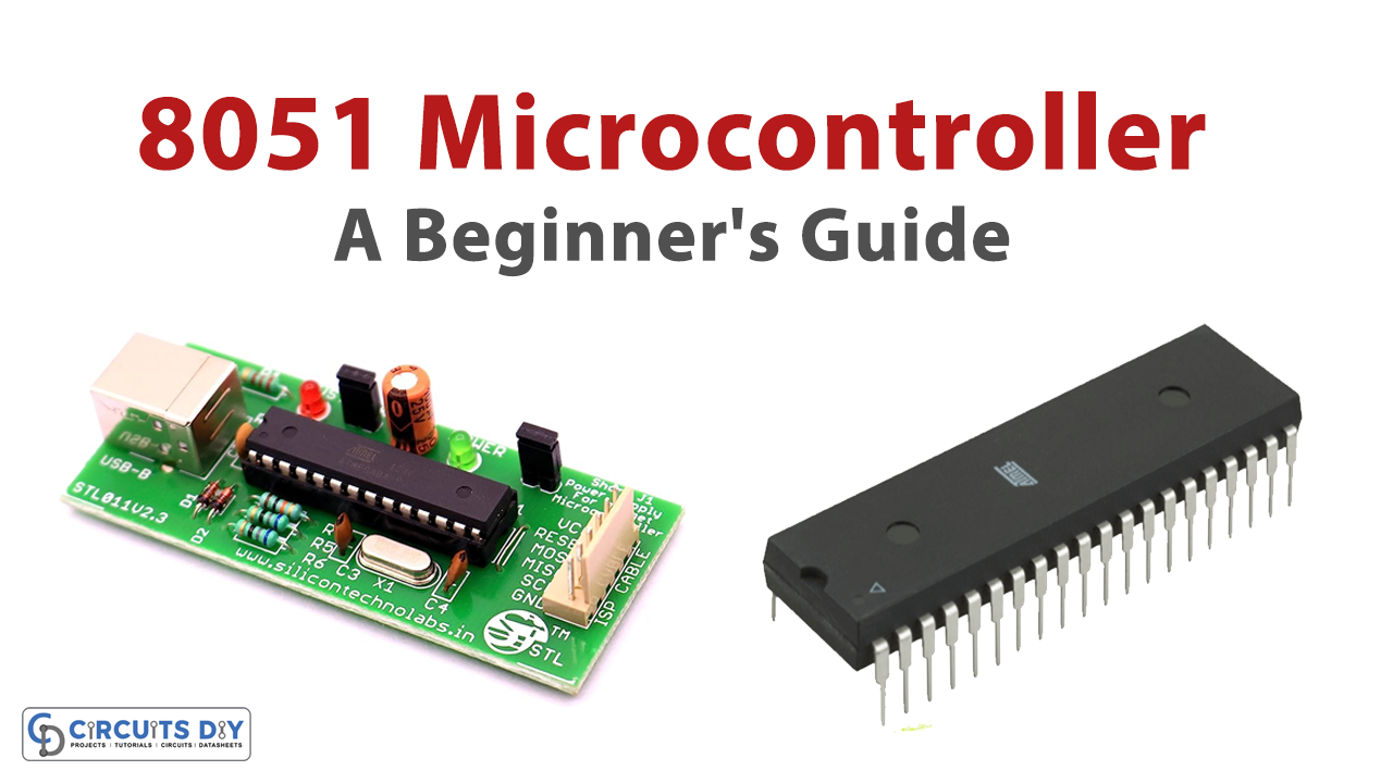
What is an 8051 Microcontroller?
In 1980 a company called Intel made a chip for embedded systems, now known as the 8051 microcontrollers. John H. Wharton set the architect of this microcontroller. Thus, it uses Harvard architecture. The 8051 Microcontroller is an integrated circuit chip having 40 pins that include CPU, memory, timers, and other peripherals ( which we will discuss below in the architecture heading).
We commonly used this in embedded systems, automotive systems, robotics, communication systems, and consumer appliances. Thus, these 8051 microcontrollers have established a renowned place in the market in terms of their operation, cost, and availability.
Before the microcontroller came in, the designers designed every device that required automatic action with the processor. Coming towards the language of the controller, Older forms of 8051 use assembly language. But now the editions also use more advanced languages like C language JavaScript or Python.
When we talk about the packages, 8051 comes in a variety of packages but the most common package is a Dual Inline Package (dip). But, it is also available in other surface-mount packaging.
To understand this 8051 microcontroller, in this article, we are going to discuss:
- History of 8051 microcontrollers.
- Features of 8051 microcontrollers.
- The architecture of 8051.
- Pin configuration of 8051.
- 8051 microcontroller programming.
- Applications of 8051 microcontrollers.
History of 8051 Microcontroller
We give a concise description of the 8051 Microcontroller and its past in the 8051 Microcontroller Introduction. The Intel 8051 Microcontroller was a replacement for the 8048 Microcontroller was Intel MSC-51 Architecture and Intel MSC-48 Architecture.
They initially designed 8051 Microcontrollers by employing N-MOS technology, but the operation of battery-powered structures and their low power consumption advanced them to the use of CMOS technology which was popular for its low power consumption. After Intel built 8051 microcontrollers they discontinued manufacturing them in 2007. But now, 8051 compatible microcontrollers are being manufactured by over 20 manufacturers, it now based all processors on the MSC-51 architecture.
Atmel (AT89C51, AT89S51), STC Micro (STC89C52), Phillips (S87C654), Infineon (SAB-C515, XC800), Silicon Labs (C8051), Siemens (SAB-C501) NXP (NXP700, NXP900), etc., are some of the 8051 microcontrollers manufactured by various manufacturers.
Silicon Intellectual Property Cores which are known as IP cores are most of the modern 8051 Microcontrollers, but some discrete 8051 Microcontroller ICs are also available. We use 8051 IP Cores in Field Programmable Gate Array (FPGAs) and System on Chip (SoCs) instead of Advanced ARM Architecture-based MCUs because of their basic architecture, low power consumption, and smaller size.
Features of 8051 microcontroller

There are tons of prominent features available in 8051 IC. We are discussing some below:
- It has 4KB bytes of on-chip program memory called ROM.
- It contains 128 bytes of data memory known as RAM.
- There are four registered banks available.
- Moreover, it has 128 user-defined software flags.
- Further, there is an 8-Bit bidirectional data bus.
- Also, the 16-Bit unidirectional address bus is there too.
- The microcontroller includes 32 general-purpose registers each having 8 bits.
- There are two or more 16-bit timers present.
- Three internal interrupts.
- Two external interrupts.
- There are four 8-Bit ports. However, a short model contains two 8-bit ports.
- 16-bit program data pointer and counter available.
The architecture of the 8051 Microcontroller
The architecture of 8051 incorporates CPU, memory, oscillators, interrupt, timer, busses, etc all we are going to discuss below.

CPU
The Central Processing Unit (CPU) is simply like any other. It reads the program from a read-only memory and performs the actions accordingly. Hence, controls and monitors the operations.
Memory Organization
The memory organization includes Random access memory (RAM), Read-Only Memory (ROM), and program memory.
- Random Access Memory: RAM is an unstable memory used to store temporary data. 8051 includes 4KB bytes of on-chip program memory called ROM.
- Read Only Memory: To store the data permanently, we use this memory. It stores the instruction and program. We first program the controller and store it permanently in ROM. and, the CPU would execute it. It contains 128 bytes of data ROM memory.
BUS
As you know, BUS sends or brings in the data from or to the peripherals. It comprises multiple wires. But it has some more functions. Thus two different busses exist in the 8051 microcontrollers.
- Data Bus: This bus is only there to transfer or receive the data from one to another peripheral. 8051 has an 8-Bit bidirectional data bus that carries the data of specific applications.
- Address Bus: This bus transfers the memory address from peripherals to the CPU. The 16-Bit unidirectional address bus is present in this microcontroller.
Oscillators
We use oscillators to generate time. And, therefore the 8051 microcontroller contains an on-chip oscillator that functions as a clock source for the CPU of 8051. The output pulses of the oscillator are stable. Hence, it sets up synchronized work for all parts of the 8051 Microcontroller.’
Interrupts
Interrupts enable the 8051 microcontrollers to monitor peculiar events in the background while performing. Hence respond to any occurrence if happened by pausing the particular program. Thus, interrupts synchronized this all. There are two types of interrupts available in the 8051 microcontrollers.
- External Interrupt: The interrupts that happen because of an outside event. There are two external interrupts in this microcontroller, INT0, and INT1.
- Internal Interrupts: These are the interrupts that are caused by the instructions. There are three internal interrupts available in 8051, TF0, TF1, and R1/T1.
Timers/Counters
We use the timers for the measurement of intervals to measure the pulse width of pulses. 8051 microcontroller comprises two 16-bit timers and counters. They again divided these counters into an 8-Bit register.
Input/ Output Ports
To connect the microcontroller with other components and peripherals, microcontrollers always need input/output ports. An 8051 contains four input and output ports to communicate with other peripherals.
Pin Configuration of 8051 Microcontroller
There are 40 pins available having four ports P0, P1, P2, and P3.
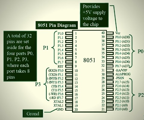
Port P0
Pin 32 to 39 belongs to port 0 port. These are the bidirectional input/ output pins. However, they don’t have an internal pull-up resistor. And, hence, you need the external pull-up resistors for them.
Port 1
Pin 1 to pin 8 belongs to port 1. These are the bidirectional input/output pins with an internal pull-up resistor.
Port 2
Pins 21 to 28 exist in port 2. Every pin is bidirectional Input /Output with internal pull–up resistors. When external memory is interfaced, PORT 2 pins work as the higher-order address byte.
Port 3
Port 3 has 8 pins from a pin 10 to 17. They specify every pin for unique work, which we describe below.
- RXD (Pin10): Serial input pin.
- TXD (pin 11): Serial output pin.
- INT0 (Pin 12): It’s an external interrupt 0.
- INT1 (Pin 13): It’s an external interrupt 1.
- T0 (Pin 14): Timer 0.
- T1 (Pin 15): Timer 1.
- WR (Pin 16): External memory write.
- RD (Pin 17): External memory read.
Other Pins
- Reset Pin: Pin 9 is an active-high reset pin.
- Oscillator Pin: Pins 18 and 19 is an external oscillator pin.
- Ground Pin: Pin 20 is the ground pin.
- PSEN: Pin 29 is the program store enable pin. It’s an output pin and using this pin, we can read external Program Memory.
- ALE/PROG: Pin 30 is an address latch that enables pin
- EA/VPP: External Access Enable Pin which allows external Program Memory.
- VCC: PIn 40 is a power supply pin.
Programming of 8051 microcontroller
We usually use Assembly language or C language for 8051 microcontroller programming. We know the software used for this purpose is Keil.
An Overview of the Keil Software
They designed the Keil 8051 Development Tools to deal with the complex problems faced by embedded software developers. Keil development tools for the 8051 Microcontroller Architecture allow every level of software developer either a beginner or a professional.
It’s free software that solves problems for an embedded program developer. Like Arduino, this software also is an integrated development environment (IDE), which includes a text editor for writing programs, and a compiler and it can create hex and Axf files.

8051 Programming on Keil
To program, you first need to download and install the Keil software.
After that open, the software, go to the project, select a new project, then select the location for the storage of your program. Name the project and save that.
From the next window, select the microchip and then click ok.
Now, from the menu, select new, and a new editor will get open.
Go to the save option to save the code. Remember to save it with the .c extension.
Now write the code.
Now from the left panel, select Source Group 1, and Add Existing Files to Group ‘Source Group 1’. After that, select the program (c file), add, and close.
Now go to the project, and select build target, it would be a project and if there would be an error, it would not. And, will build it when the errors get corrected.
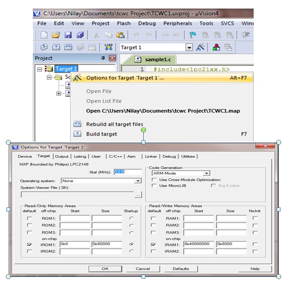
Now click on Target1 from the left panel and select Options for Target ‘Target1’. Then set the MHz value to 11.0592. Checkmark on the Use On-Chip ROM. Then go to the output tab. In this tab, check to Create Hex File and click OK. Then build it again.
Now upload this hex file on your 8051 microcontroller IC.
Blinking LED Example of 8051 microcontroller
Here we are with the circuit through which you can kick-start learning the 8051 microcontrollers. Hence we will make a blinking light LED circuit.
Components Required
| S. No | Components | Qty |
|---|---|---|
| 1. | IC (AT89C51) | 1 |
| 2. | Resistors (470R, 10K) | 1, 1 |
| 3. | Ceramic Capacitors (22pf, 10uf) | 2, 1 |
| 4. | LED | 1 |
| 5. | Crystal Oscillator | 1 |
Circuit Diagram

Code
#include<reg51.h>
sbit LED_pin = P2^0; //set the LED pin as P2.0
void delay(int ms){
   unsigned int i, j;
   for(i = 0; i< ms; i++){
      // Outer for loop for given milliseconds value
      for(j = 0; j < 1275; j++){
         //execute in each milliseconds;
      }
   }
}
void main(){
   while(1){
      //infinite loop for LED blinking
      LED_pin = 0;
      delay(500); //wait for 500 milliseconds
      LED_pin = 1;
      delay(500); //wait for 500 milliseconds
   }
}
Working Explanation
First, you need to assemble the circuit. Connect the circuit according to the above-given diagram. After that, write the above-given code on your Atmel studio software. Compile and burn the code into your 8051 microcontroller IC. Give power to the circuit and you will observe the blinking of LEDs.
Applications of 8051 Microcontroller
- Automobiles applications
- For Engine Control.
- Transmission Control.
- Temperature Control
- Consumer Appliances.
- In TV Tuners.
- For Remote control systems.
- In computers.
- In modern Sewing Machines.
- Communication Systems
- In Mobile Phones.
- Answering Machines
- In Paging Devices, etc.
- In defense systems.
- It has applications in robotics
- In medical applications, etc.