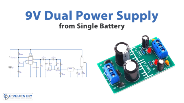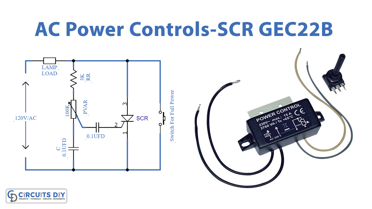
Introduction
SCR, Silicon Controlled Rectifier which is also popular as a thyristor is a solid-state current controlling component having four layers and three junctions. These junctions or terminals are known as anode, cathode, and gate. It is commonly used in AC power control circuits. For example, AC motor speed control, dimmer lighting control dimmers, etc. The SCR conducts when the input signal reaches the firing angle of its gate terminal. To understand the circuit, in this tutorial, we have come up with a circuit called “Ac Power Controls-SCR”
Hardware Required
| S.no | Component | Value | Qty |
|---|---|---|---|
| 1. | SCR | GEC22B | 1 |
| 2. | SPST Switch | – | 1 |
| 3. | Variable Resistor | 100K | 1 |
| 4. | Capacitor | 0.1uF | 1 |
| 5. | Resistor | 3K | 1 |
| 6. | Lamp | – | 1 |
Circuit Diagram
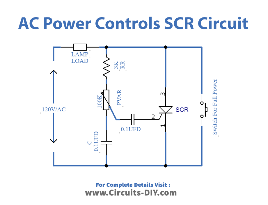
Working Explanation
In this Ac Power Controls-SCR, the SCR turns on when a low voltage AC input signal is provided gate terminal of the SCR by a simple resistor network that also includes the potentiometer. When the input applied input signal reaches the gate firing potential of SCR, SCr will turn ON. Now, when the SCr turns ON it starts conducting and continues to conduct till the AC signal wave lessens to just above zero volts. When the current flowing between cathode and anode decreases to a value less than the holding current, SCR goes into a nonconducting state and remains non-conductive during the whole negative half cycle of the AC wave because right now it is reverse biased blocking mode The SCR starts conduction again when the next positive half-cycle comes and wave signal reaches the firing potential of gate terminal.
Application and Uses
- They can be used in different controlling devices or circuits