Alternating current power has so many uses in our daily lives. It is an AC power that enables our home equipment and appliances to work. Our home appliances like lights, fans, refrigerators, ACs, washing machines, AC motors, and induction motors, all need an AC supply. However, some of them like fans and motors require speed control. And, for this, there are some electronic components available that help to control the speed of AC power. One of them is TRIAC. So, in this tutorial, we are going to “Ac Power Controls-TRIAC”
The name TRIAC is coming from the TRI means three and AC means Alternating current because it’s a three-terminal device and can both positive and negative cycles of AC signals. There are tons of applications of TRIAC control circuits ad can be found everywhere. One of them is the fan dimmer at your home. This small component can control bidirectional pulses, thus known as a bidirectional switch. Moreover, TRIAC can be made by two separate but equivalent SCR if connected in an inverse parallel configuration.
Hardware Required
| S.no | Component | Value | Qty |
|---|---|---|---|
| 1. | TRIAC | BT136 | 1 |
| 2. | DIAC | DB3 | 1 |
| 3. | Variable Resistor | 100K | 1 |
| 4. | Capacitor | 0.1uF | 1 |
| 5. | Resistor | 3K | 1 |
| 6. | Lamp/LED | – | 1 |
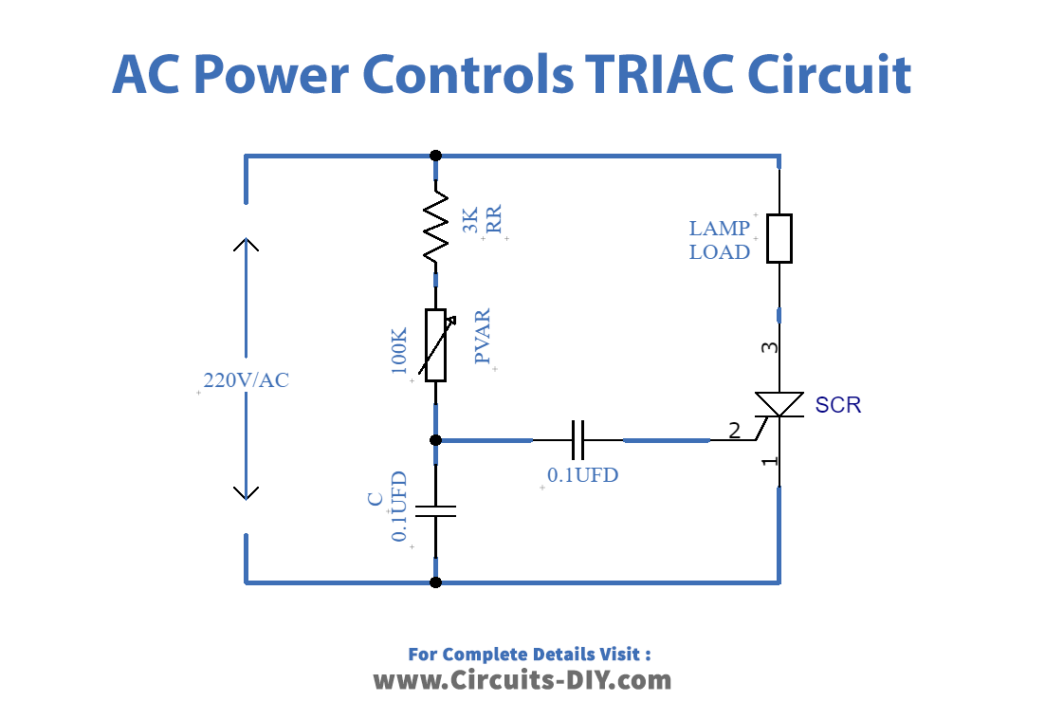
Circuit Diagram
Working Explanation
In this Ac Power Controls-TRIAC, the TRIAC is working as a switch. The current would flow through the load whenever TRIAC turns ON. Initially at the positive half cycle when the TRIAC is OFF, the current flows through the path of resistor RR and potentiometer RVAR. This resistor and potentiometer charge the capacitor C wired in the circuit. With time voltage gets increased across the capacitor and hence, the time would come when the voltage across it would beat the breakthrough voltage of DIAC DB3.
At this point, DIAC gets fired and current starts flowing through that and the capacitor starts discharging through the DIAC gate. The discharging current of this capacitor is now enough to turn on the TRIAC and TRIAC starts conducting and current flows through the load. The TRIAC remains in conducting mode until the TRIAC’s current gets less than the holding current. At this point when the holding current is more than TRIAC, the TRIAC turns OFF.
Now at the negative half cycle, the current would flow through the capacitor, again the capacitor will charge but with different polarity. And, again the DIAC gets fired and the capacitor starts discharging but discharging happens opposite to the conventional current. However, as you know that TRIAC does work with both polarities, no matter whether the current is towards the gate or away from the gate. SO again TRIAC turns ON and the current flows through the lamp until the holding current gets increased than the TRIAC current. This is how the circuit works. The load intensity can be varied by the potentiometer.
Application and Uses
- Mainly, the circuit can be used to control AC appliances.
- For example, to control the speed of the fan.
- Also, to vary and change the light intensity of AC lights and lamps.
- With some further modification, you may also control AC motors through this circuit.