Introduction
In this tutorial, we are going to build the “Phase-Neutral-Earth Fault Indicator Circuit.” A device called a phase-neutral-Earth fault indicator checks the electrical current moving through a circuit and alerts the user when there is an abnormality. This may be the result of several things, such as wiring or equipment malfunctions, or simply a shift in the circuit’s load.
Although some more advanced types may also offer a digital readout, the indication often takes the form of a light or sound. It should be noted that a Phase-Neutral-Earth Fault Indicator does not signal a serious scenario, but rather shows the states and imbalances that should be checked.
With the use of this circuit, you can identify the open earth, phase, or neutral reverse in the power source. We can build this circuit utilizing basic parts like resistors and LEDs. The suggested phase, neutral, and earth indication circuit has a fairly simple design.
Hardware Required
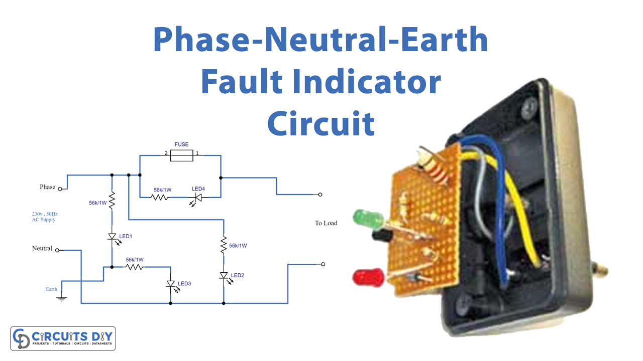
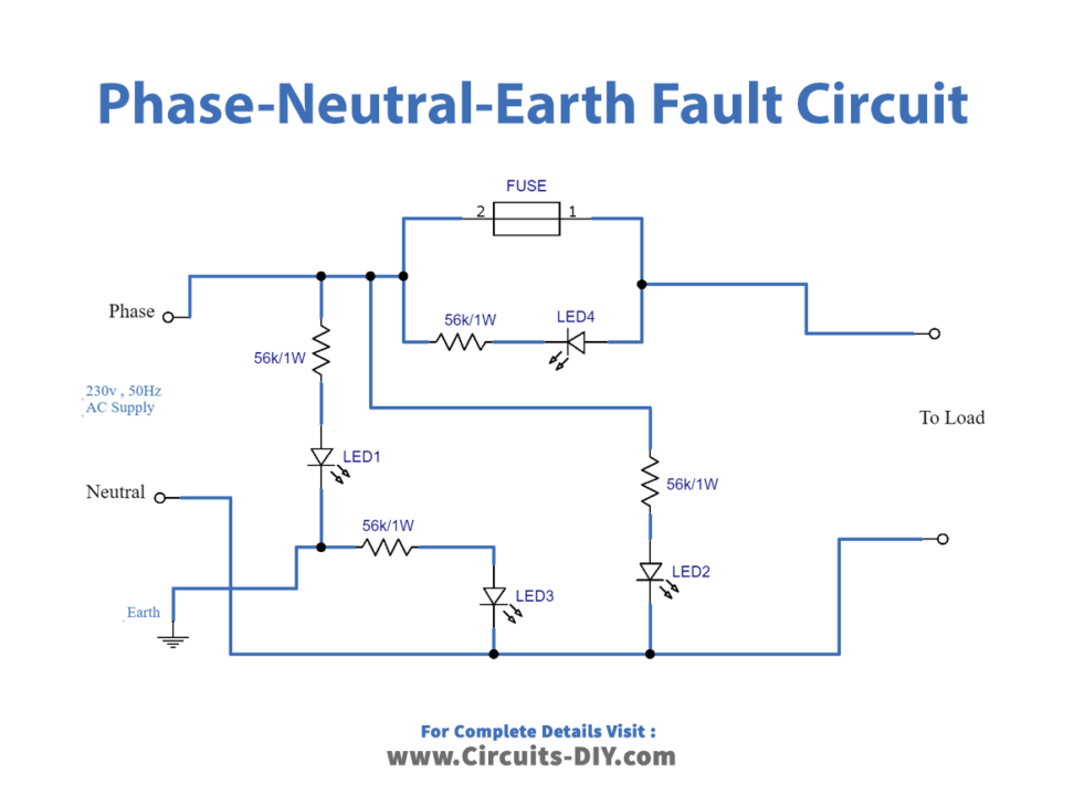
Circuit Diagram
Working Explanation
Here, there are four red LEDs utilized, and a 56K/1W resistor is employed. Through a resistor, LED1 is connected to the phase and the earth. LED2 is connected between the Phase and the Neutral. Between Earth and Neutral is where LED3 is linked. LED 4 is positioned parallel to the fuse, and when the fuse blows when an appliance is plugged in, it flashes. Now the circuit works in a way that the state of the AC power supply will be shown by these three LEDs.
- If Phase Neutral earth is wired correctly LED 1 and LED 2 turn ON
- For the wrong polarity of Phase/Neutral LED 2 and LED 3 turns ON
- If the status is open Earth or Neutral all three LEDs turn ON
- In case of blown a fuse, only LED 4 turns ON
Application and Uses
- The circuit serves as a high-voltage current protection for appliances.