Introduction
To split the audio signals into two frequency bands for any audio applications, designers have created the circuit. The circuit is popularly known as the crossover circuit. The central purpose to practice this circuit is in the speakers. The speakers don’t give the appropriate signals when the frequency changes from low to high. Hence, distortion occurs. The circuit divides the input into two frequency bands that are individually get amplified by the operational amplifiers, wired into the circuit. Generally, cross-overs are of two kinds, The active crossover circuit, and the passive crossover. In this article, our main motive is to make an active crossover circuit.
Active Crossover
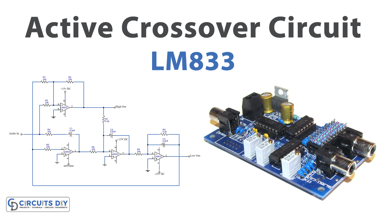
Active crossover circuit uses the active components in their filters. Further, the circuit incorporates the operational amplifiers to amplify the magnitude of the coming signal. Besides, the circuit has two power amplifier stages, for high and low bands of frequencies. Moreover, the active cross-over is more favorable than the passive, one because it saves a lot of energy. Now, coming toward our circuit, so to make our circuit, we are using LM833 operational amplifiers. Remember to use a dual power supply as the Ic supports the dual supply. Also, make sure to mount the ICs on their holders.
Hardware Required
| S.no | Component | Value | Qty |
|---|---|---|---|
| 1. | PCB | – | 1 |
| 2. | IC | LM833 | 2 |
| 3. | Resistors | 6.2K, 24K | 2, 7 |
| 4. | Capacitors | 6.8nf | 3 |
| 5. | Dual power supply | 15V | 1 |
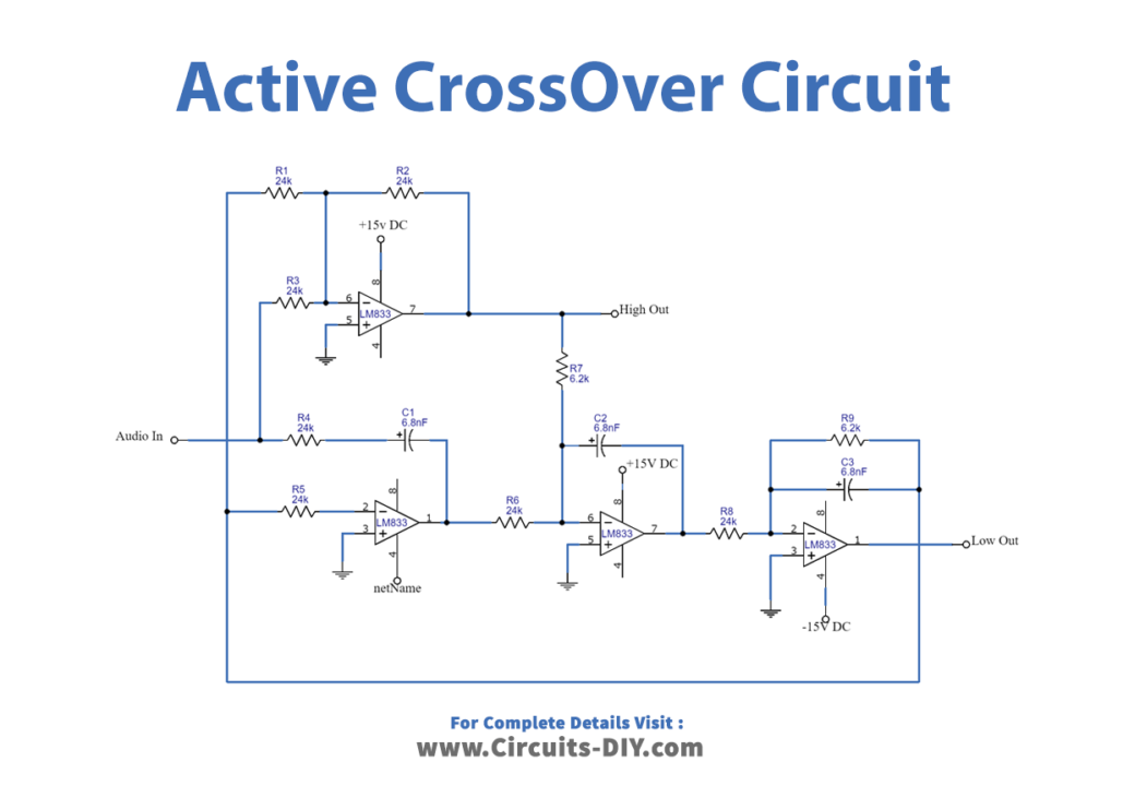
Circuit Diagram
Working Explanation
This active crossover circuit requires four opamps. Therefore we are using two LM833 ICs. The circuit contains two parts, the high pass filter, and the low pass filter. So, here, IC1 a is making the low pass filter which out would be available at pin 1 of an IC. While the high frequency would be available at pin 7 of an IC. Moreover, the cross-over frequency for this circuit is 1KHz.
Application and Uses
This circuit can be used and applied for any audio application.