
What is a Four Siren Sound Generator?
A four-siren sound generator is a simple siren circuit that is mostly used in devices such as Police sirens, Fire engine sirens, Ambulance sirens, etc. It can produce up to four distinct sounds varying in intensity & pitch. So, in today’s tutorial, we will go over a step-by-step process on how to design a Four Siren Sound Generator using the UM3561 Sound Generator IC.
The heart of this circuit is the UM3561 sound generator IC. UM3561 is an outstanding ROM (Read Only Memory) IC. The main function of this chip is to produce different siren tones like Ambulance, Police, machine gun, and Fire brigade siren sound. The typical operating voltage of UM3561 is 3V and the operating Current is 150μA. The output current of UM3561 is 3mA. It is a low-cost IC mainly designed for toy applications.
JLCPCB is the foremost PCB prototype & manufacturing company in china, providing us with the best service we have ever experienced regarding (Quality, Price Service & Time).
Hardware Components
The following components are required to make Four Siren Sound Generator Circuit
| S.no | Component | Value | Qty |
|---|---|---|---|
| 1. | Sound Generator IC | UM3561 | 1 |
| 2. | IC Base | 8 – pin | 1 |
| 3. | Transistor | BC547 | 1 |
| 4. | Four Siren Sound Generator PCB | AllPCB | 1 |
| 5. | Pushbutton | – | 3 |
| 6. | Loudspeaker | 8 Ohms | 1 |
| 7. | Resistor | 220K, 220 Ohm | 2 |
| 8. | Terminal Block Connector | 3.5mm | 1 |
| 9. | Soldering Iron | 45W – 65W | 1 |
| 10. | Soldering Wire with flux | – | 1 |
| 11. | DC Battery | 3V | 1 |
| 12. | Battery Clip | – | 1 |
| 13. | Soldering stand | – | 1 |
| 14. | Jumper wires | – | As per need |
UM3561 Pinout
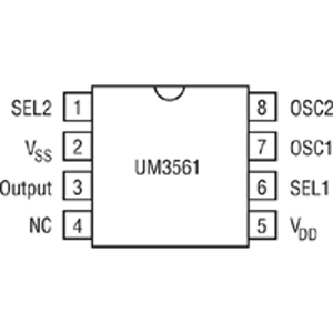
For a detailed description of pinout, dimension features, and specifications download the datasheet of UM3561
BC547 Pinout

For a detailed description of pinout, dimension features, and specifications download the datasheet of BC547
Useful Steps
1) First, Solder all the resistors on the PCB Board,

2) Solder the 8 – pin IC base on the PCB board. After that, Solder the BC547 transistor on the PCB board.

3) Solder the three pushbuttons on the PCB board.

4) Solder the I/O block connectors on the PCB board.

5) Connect a 4 Ohms speaker to the output of the circuit. After that connect a 3V battery to the input block connector of the circuit.
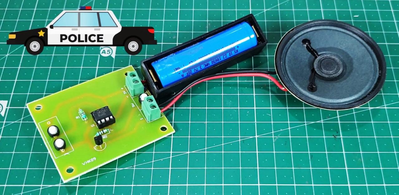
6) Power up & test the circuit

Four Siren Sound Generator Circuit
Working Explanation
The working of this four-siren sound generator is based on the operation of the UM3561 IC. here, the oscillator generates the necessary clock pulse for the operation of the IC. The frequency of the oscillation is determined by the resistor connected to pin 7 (OSC1) & pin 8 (OSC2) of the IC.
A 220K Ohm resistor is connected across pins 7 & 8 to acquire the output. The output generated by the UM3561 IC is not enough to drive the 8 Ohm loudspeaker. In order to amplify the output of the UM3561 IC, a BC547 transistor is used at Pin 3 (OUT) of the IC.
Applications
- Commonly used in devices like small toy cars & trucks.
- Also used in the sirens of law enforcement & medical (EMT) vehicles such as police cars & ambulances respectively.