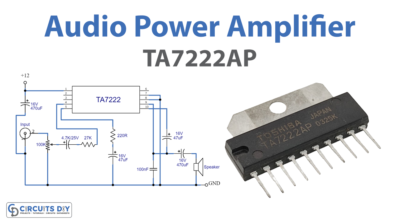
The audio amplifier is the basic circuit configuration that is required to amplify, the audio signal received through a device like a microphone or the audio signal that is to be transmitted out through a speaker/ radio device/wireless transmitter, etc. Here is a simple 5.8W Audio power amplifier circuit designed with very few external parts. The main part of this circuit is Toshiba TA7222AP amplifier IC. It has adjustable closed loop gain and high sustaining over voltage with high power and low distortion output. And operating supply given to this circuit may vary between 8 to 18 volts.
Hardware Required
| S.no | Components | Value | Qty |
|---|---|---|---|
| 1. | IC | TA7222AP | 1 |
| 2. | Resistor | 100KΩ,27KΩ,220Ω | 1,1,1 |
| 3. | Capacitor | 470uF/16V,4.7uF/25V,47uF/16V,100nF | 2,1,2,1 |
| 4. | Buzzer | – | 1 |
| 5. | Connecting Wires | – | – |
| 6. | Power Supply | 12V | 1 |
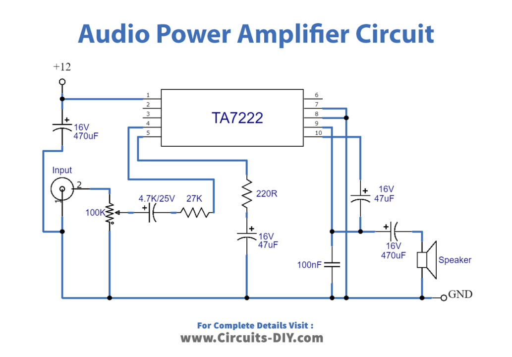
Circuit Diagram
Working Explanation
As we can see that the main part of the circuit is Toshiba TA7222AP amplifier IC. It is designed to give 5.8W output power. Here +12V is used to bias the IC through pin1 and the pin numbers 2, 3 & 6 are kept empty. The audio input signal through the variable resistor is given to pin number 4, by which we can control input amplitude. And the loudspeaker is connected with output pin9 with a 470µF capacitor and bootstrap signal through a 47µF capacitor (This bootstrap signal capacitor c5 depend on the load connected at the output). This circuit is suitable for 2Ω to 8Ω loudspeaker load at the output, here R1 resistor is used as the volume controller.
Applications
It can be used in almost all consumer electronic devices ranging from microwave ovens, headphone drivers, televisions, mobile phones, and home theatre systems to theatrical and concert reinforcement systems.