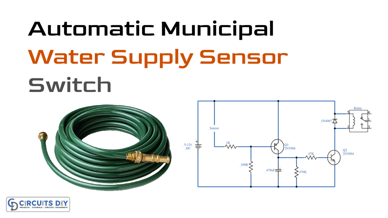
Here is a simple and interesting project of an Automatic municipal water supply sensor switch circuit. The purpose of this circuit is to sense or detect when the water comes into the municipal water supply pipe and activates an alarm or a water pump. The circuit is simple it uses two transistors and some other discrete components. Two points are marked in the circuit diagram where the sensor should be placed at the mouth of the municipal supply line.
Make sure to use the relay with the same voltage as the operating voltage, a 12V relay won’t work with a 5V supply.
Hardware Components
The following components are required to make an Automatic Water Supply Circuit
| S.no | Component | Value | Qty |
|---|---|---|---|
| 1. | Input Supply DC | 5-12V | 1 |
| 2. | Sensor | – | 1 |
| 3. | Transistor | 2N3906, 2N3904 | 1 |
| 4. | Electrolytic Capacitor | 470µF | 1 |
| 5. | Relay | – | 1 |
| 6. | Diode | 1N4007 | 1 |
| 7. | Resistor | 1K, 100K, 47K, 470K | 1, 1, 1, 1 |
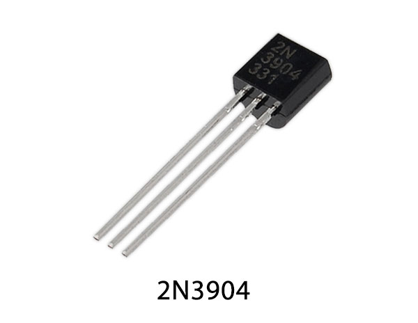
2N3904 Pinout

For a detailed description of pinout, dimension features, and specifications download the datasheet of 2N3904
2N3906 Pinout

For a detailed description of pinout, dimension features, and specifications download the datasheet of 2N3906
Automatic Water Supply Circuit

Working Explanation
The operating voltage of this circuit is 5 to 12 volts DC. When the sensor detects water the resistance between them is decreased and it starts conducting and activating the circuit. On the activation of the circuit, the transistor Q1 activates, and the timer circuit is switched on. The timer circuit is built around the transistor Q2 2N3904, it remains activated for 45 seconds. The main purpose of using this timer circuit is to switch on the relay continuously at all times when there is air in the pipeline.
Applications and Uses
- Water pumps
- Tanks
- Pipelines