In this tutorial, we are going to make a “Battery charger circuit diagram with auto cut-off”. A battery charger is a device that recharges a depleted electrolyte by using direct current. After it has replenished all the electrolytes, the battery’s current supply should come to a halt. As a result, a battery’s performance is determined by the charging process. Nowadays we have become more reliant on batteries, as we require batteries for cell phones, emergency lights, car batteries, UPS batteries, and other fundamental electronic circuits.
They make gadgets more portable, making them more accessible to users. Here we design a battery charger circuit diagram by implementing an adjustable voltage regulator LM317 with an auto cut-off feature. This circuit will give adjustable DC supply output and charge battery ranges from 6 volts to 12 Volts. The LM317 is a monolithic integrated IC, it is a positive adjustable voltage regulator that comes in three different packages. It can deliver 1.5A of load current, and the output voltage can be adjusted from 1.2 to 37 V.
Hardware Required
| S.no | Component | Value | Qty |
|---|---|---|---|
| 1. | Transformer | 0 – 15V | 1 |
| 2. | Diode | 1N4007 | 5 |
| 3. | IC | LM317 | 1 |
| 4. | Zener Diode | 12V/1W | 1 |
| 5. | Transistor | BD139 | 1 |
| 6. | Resistor | 2KΩ,1KΩ,220Ω,10Ω/5W | 1,1,1,1 |
| 7. | Capacitor | 1000uf,0.1uf | 1,1 |
| 8. | LED | – | 2 |
| 9. | Variable Resistor | 10KΩ | 1 |
| 10. | Connecting Wires | – | – |
| 11. | Battery | 12V | 1 |
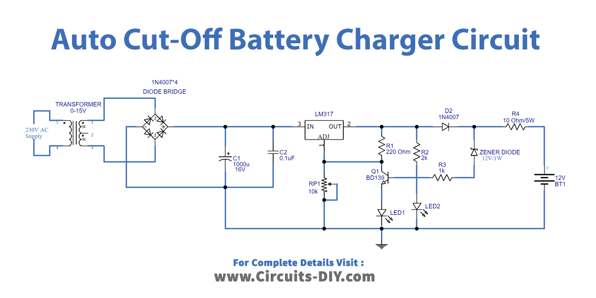
Circuit Diagram
Working Explanation
In this circuit, to step down the AC power supply we have used a (230V to 15V) step-down transformer. And then the bridge rectifier (1N4007 X 4) converts the AC supply into a DC supply. Here C1 and C2 capacitors perform filter operation then finally IC1 LM317 regulates the DC power supply. Variable resistor changes the supply to adjust the pin of the voltage regulator and it changes the output voltage range. Now green LED represents the charging condition and the red LED indicates the fully charged battery.
When the battery becomes fully charged, reverse voltage through the Zener diode (12V) flows to transistor BD139 (The transistor detects when the battery is fully charged. When the battery is being charged, it turned a charge indicator LED on. And turns off when the charging is complete) base and makes it turn ON. Now due to the conduction in the transistor adjust the pin of the voltage regulator connected to the ground and cut the output voltage from the regulator. These are the chargers that continually monitor the charging voltage of the battery and switch off the charging voltage when the battery reaches full charge. Connect the heat sink with voltage regulator LM317 to avoid thermal runaway.
LM317 VO Calculation
LM317 regulator gives variable output voltage and it can be varied by using Adjust pin. We can calculate VO from IC LM317 as:
VO = VREF (1 + R2/R1) + IADJ R2
It can be modified depending on this circuit design as,
VO = VREF (1 + VR1 / R1) + I ADJ VR1
Here VO represents the output voltage from the regulator IC.
Applications
We can use a battery charger for a variety of DC appliances like DC fans, portable juicer makers, vacuum cleaners, etc.