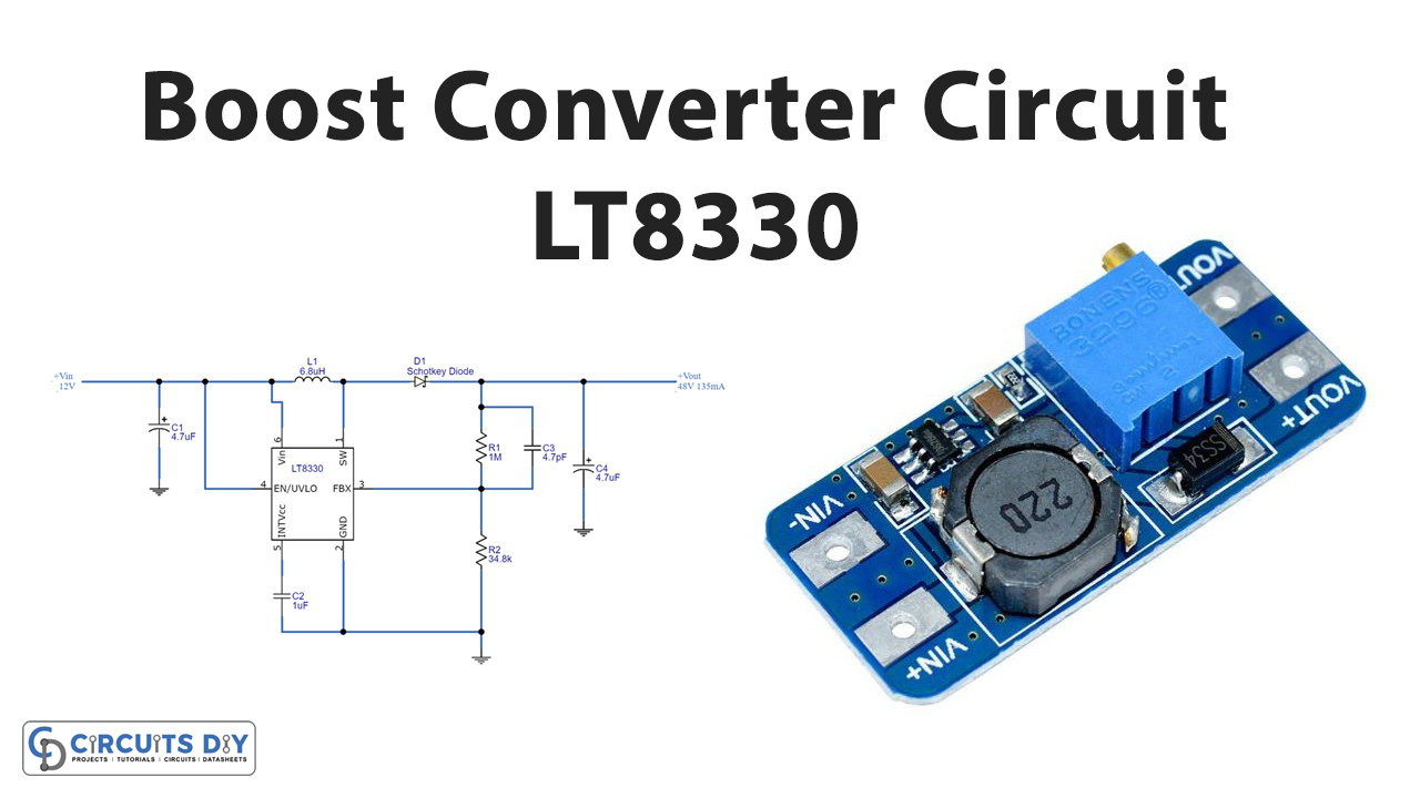
Introduction
To boost the input voltage at the output load, the circuit commonly known as a voltage booster is used. As the name implies, it takes the input voltage and with the help of some components transforms that voltage into high voltage. The circuit can be made using different methods like inductors, capacitors, semiconductor switches, etc. But, for efficient output, some boost converter ICs are also available in the electronic market. Hence, we will use one of them in our project. In this tutorial, we are going to “Boost Converter Circuit”. To make this circuit we are using the boost converter LT8330 IC.
Hardware Required
| S.no | Component | Value | Qty |
|---|---|---|---|
| 1. | IC | LT8330ES6TR | 1 |
| 2. | Schottky Diode | PMEG6010CEJ | 1 |
| 3. | Inductor | 6.8μH | 1 |
| 4. | Capacitors | 4.7μF, 1μF, 4.7pF | 2, 1, 1 |
| 5. | Resistor | 1MΩ, 34.8KΩ | 1, 1 |
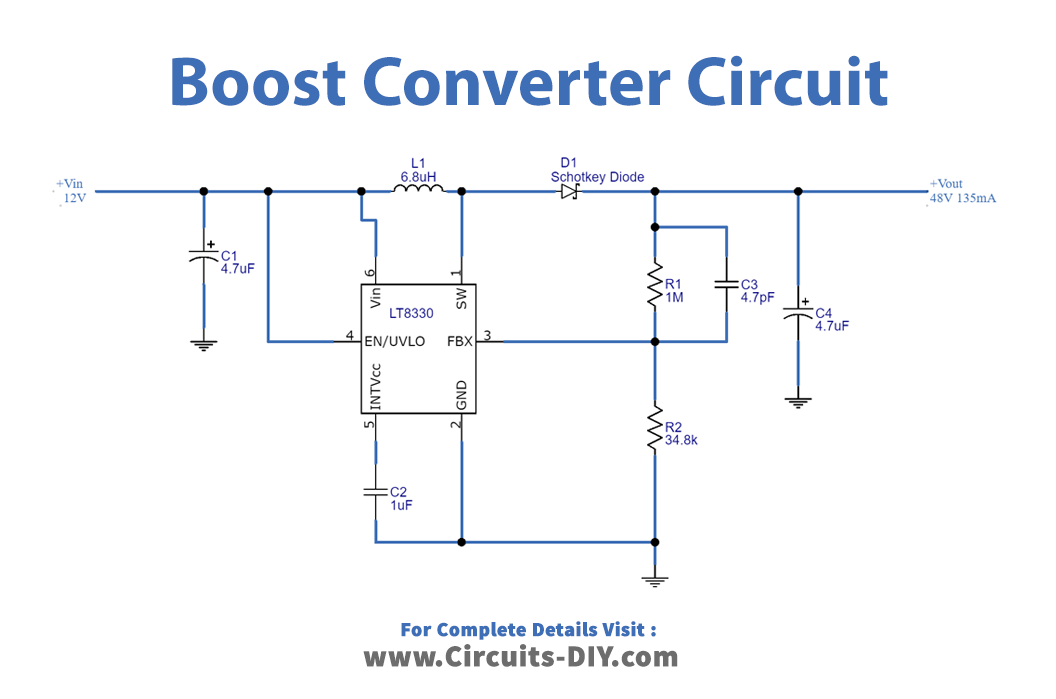
Circuit Diagram
Working Explanation
In this Boost Converter Circuit, we are using the LT8300 IC. The IC LT8330 is a current mode DC to DC boost converter proficient in generating both positive or negative output voltages by employing a single feedback pin. It consumes 6 microamperes of quiescent current, which makes it a more promising use. Positive or Negative output can be achieved by the single feedback pin. The possesses a fixed 2MHz switching frequency. When the input of 12V is given to this IC while connecting all the components present in the circuit, the 48V output would be observed across capacitor C4.
Application and Uses
- Portable electronic devices use this circuit.
- Telecommunication devices.
- Consumer electronic devices.