Overview
A portable USB hard drive serves as an efficient means to back up data, yet what if your USB ports lack the necessary power to drive the device? The solution lies in a modified rendition of the Silicon Chip USB Power Injector. Over time, I have relied on a portable USB hard drive to safeguard work-related data. Like most such drives, it draws power directly from the USB port without requiring an external plug pack supply.
However, it relies on two USB ports for power since a single port can’t deliver enough current. This is facilitated by a specialized USB cable included with the drive, featuring two connectors on one end, forming a “Y” configuration (refer to the image). One connector manages both power and data, while the other focuses solely on the power supply. During operation, these connectors are plugged into adjacent USB ports, ensuring the drive receives power from both simultaneously.
Typically, an external USB hard drive is powered by connecting two connectors from a special USB cable into adjacent USB ports on the computer, thus utilizing power from both ports. As per USB standards, each port can supply up to 500mA at 5V DC, theoretically sufficient to power a portable USB hard drive when connected in parallel.
Regrettably, this wasn’t the case in my situation. While the USB drive functioned well with various work computers, it failed to operate on my home machine. When plugged into the front-panel USB ports, the drive emitted a distinct chirping sound as it struggled to spin up, indicating an unsuccessful attempt. Although Windows XP acknowledged a device being connected, it couldn’t recognize the device or the drive.
The same outcome occurred when the drive was connected to rear-panel ports. This issue wasn’t unique to this particular drive; a newly acquired Maxtor OneTouch4 Mini drive also failed to power up correctly on my home computer despite functioning flawlessly on multiple work computers.
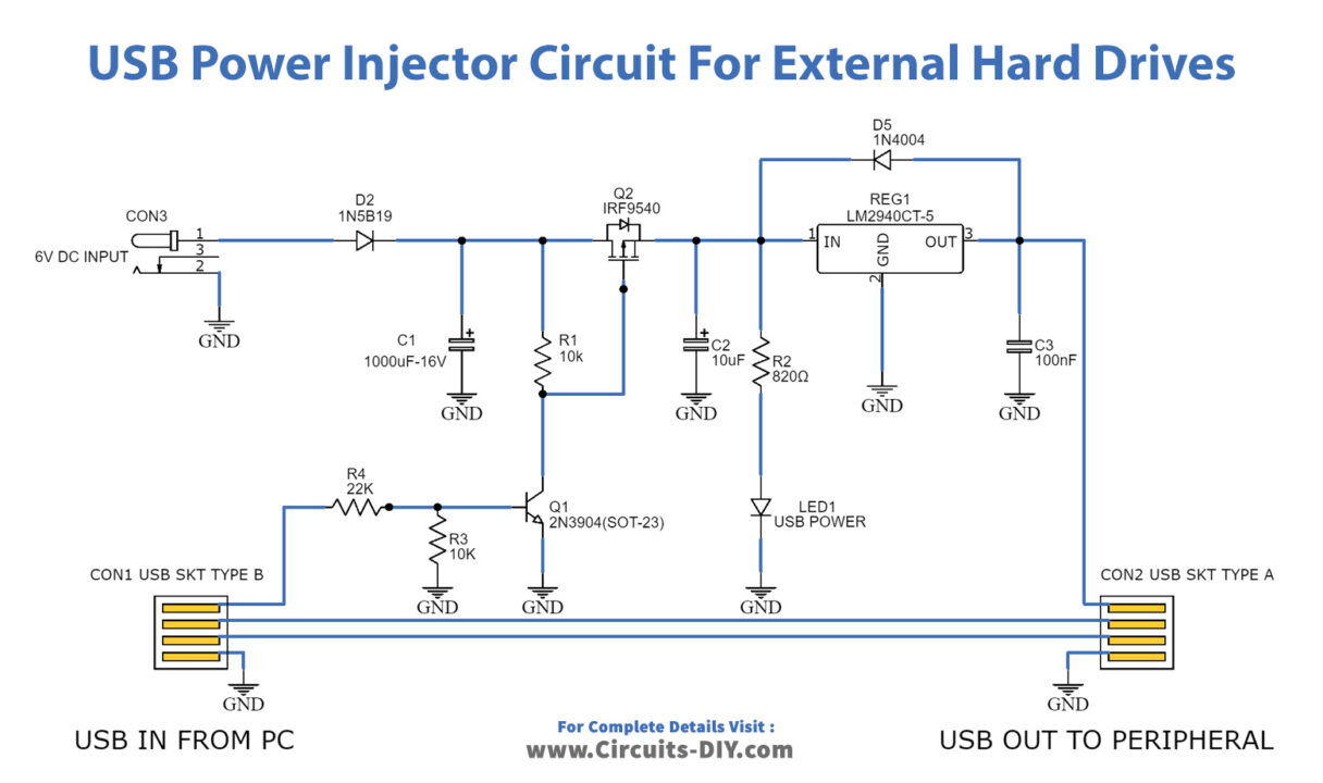
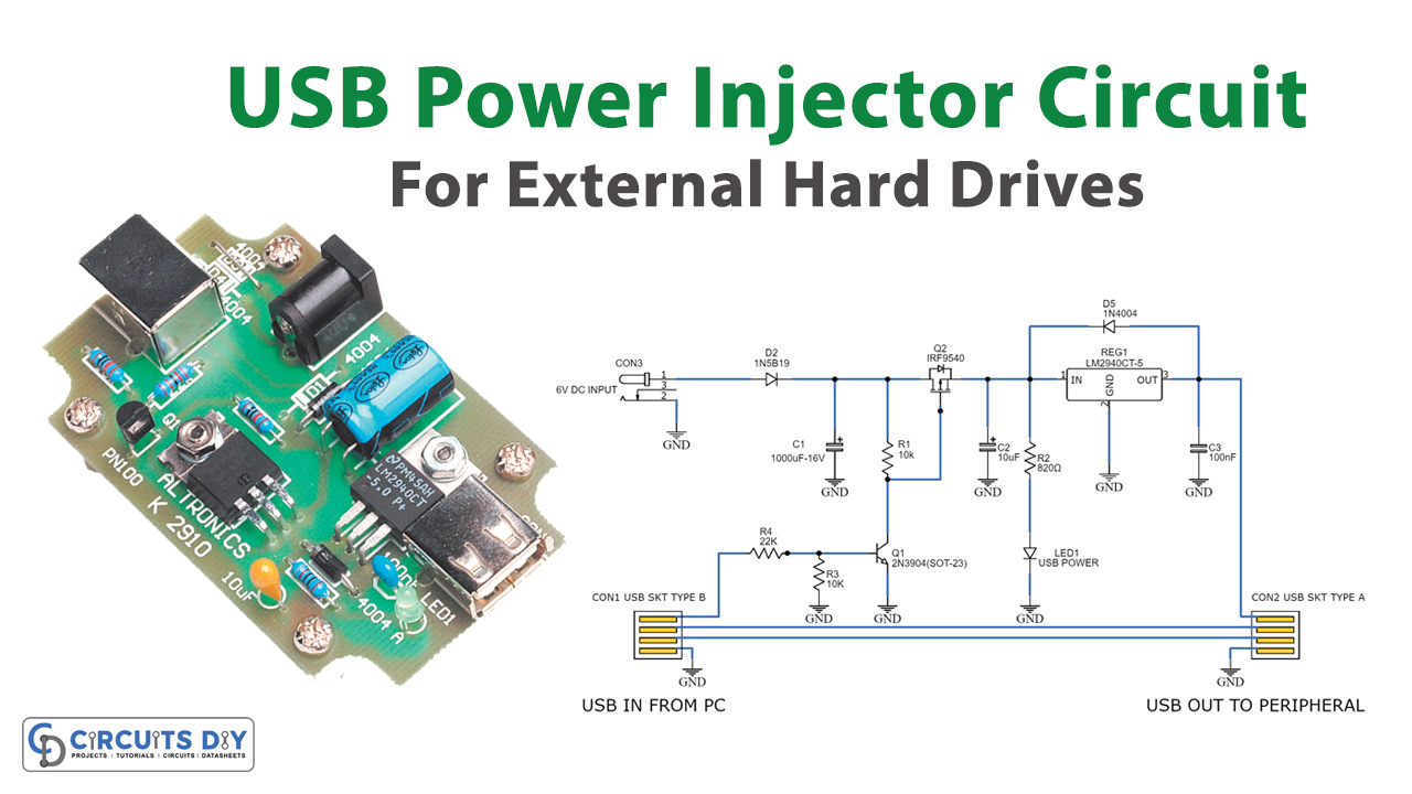
The updated USB Power Injector essentially comprises a switch and a 5V regulator. The Vbus supply from USB socket CON1 triggers transistor Q1, subsequently activating power Mosfet Q2. This, in turn, supplies a regulated 6V DC from an external plug pack to regulator REG1, providing 5V to USB socket CON2.
Hardware Components
You’ll need the following hardware components to get started:
| S no | Components | Value | Qty |
|---|---|---|---|
| 1 | Integrated Circuit IC | – | 1 |
| 2 | Transistors | – | 1 |
| 3 | Polar Capacitors | – | 1 |
| 4 | Non-Polar Capacitors | – | – |
| 5 | Resistors | – | 1 |
| 6 | LEDs | – | 1 |
| 7 | Power Supply | 9V | 1 |
Schematic