Introduction
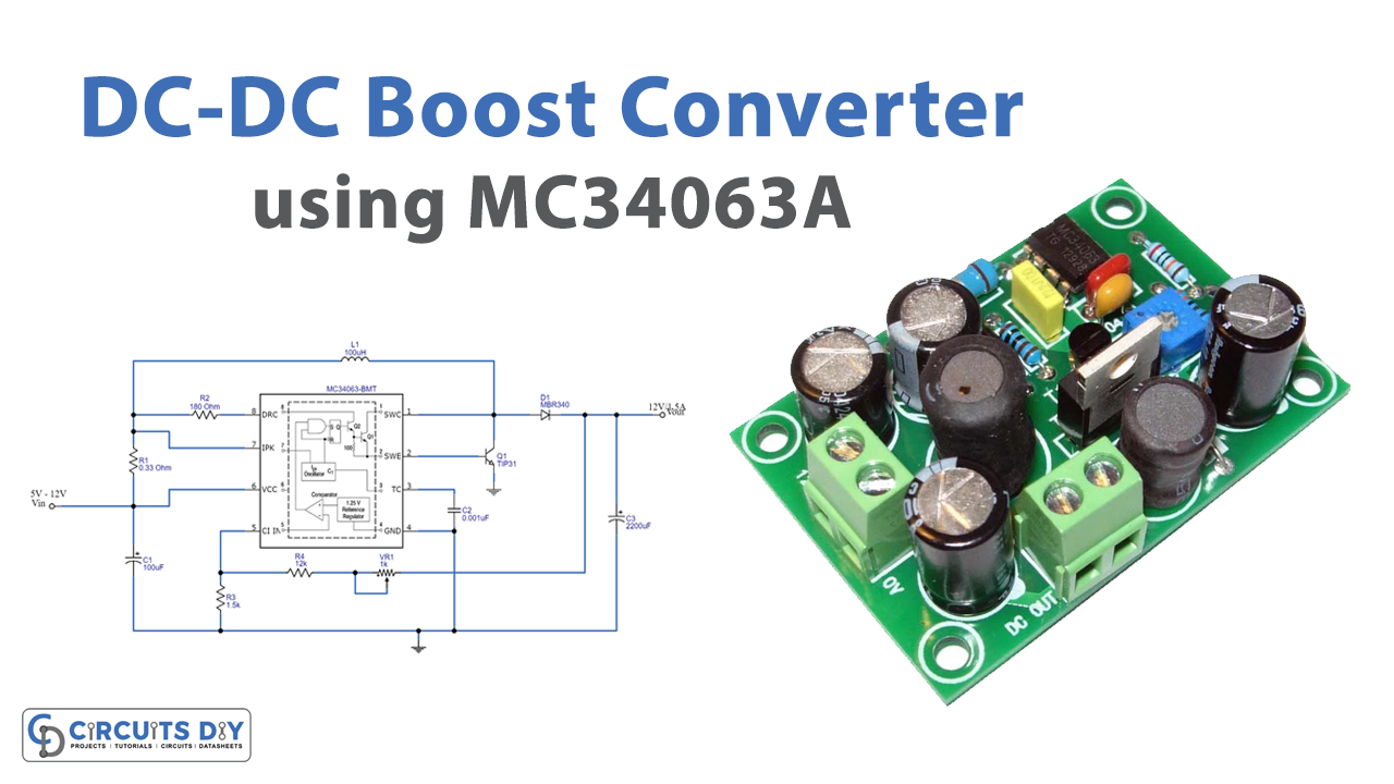
Sometimes while making the circuits, we get into a troublesome situation where we want some more supply than the power supply available. For example, we only have 3V DC available but we need 9V or 12 V DC. The circuit known as the “boost converter” gets used. It helps to boost up the input DC voltage and provide it at the output side so that it may get used by the other device that needed the greater voltage. Conversion from lower to higher voltage is not that much difficult as we have already learned about the AC to DC converter. But, this circuit is about DC to DC conversion. In this tutorial, we are going to “DC-DC Boost Converter using MC34063A”
Hardware Required
| S.no | Component | Value | Qty |
|---|---|---|---|
| 1. | IC | MC34063A | 1 |
| 2. | Diode | MBR340 | 1 |
| 3. | Inductor | 100uH | 1 |
| 4. | Transistor | TIP31 | 1 |
| 5. | Potentiometer | 1K | 1 |
| 6. | Electrolytic Capacitor | 100uF, 2200uF, 0.001uF | 1, 1, 1 |
| 7. | Resistor | 0.33 Ohm, 1.5K, 12K, 180 ohms | 1, 1, 1, 1 |
| 8. | Battery | 12 | 1 |
Circuit Diagram
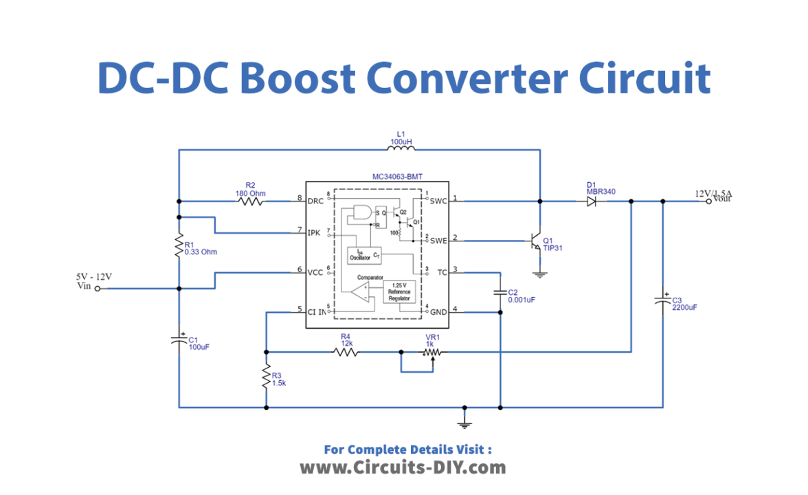
Working Explanation
This DC-DC Boost Converter using MC34063A gives the output of 12V/1.5A from a minimum 5V DC input. The circuit has a step-up DC-DC converter IC MC34063A as its major component can take input from 3V to 40V and produces an output current range of up to 1.5A with Adjustable Output Voltage. The IC also has a current limiting possibility. Values of resistors R1 and R2 handle the internal oscillating frequency and potentiometer VR1 has control over efficiency because we connect it between the output and internal comparator. The circuit also includes the inductor L1 (100µH) which you can also make through a coil with 30 turns of 22 AWG. We can use this circuit to step up the DC supply from batteries.
Application and Uses
- Photovoltaic cells can use these boost converter circuits.
- In battery power supplies, etc.
- Different electronic devices use this circuit.
- Telecommunication devices.
- Consumer electronic devices.