CD4046 belongs to the CD4000 IC series. The CD4046 micropower phase-locked loop (PLL) consists of low power, linear, voltage-controlled oscillator (VCO), a source follower, a Zener diode, and two-phase comparators. The two-phase comparators have a common signal input and a common comparator input. The signal input can be directly coupled for a large voltage signal, or capacitively coupled to the self-biasing amplifier at the signal input for a small voltage signal. The IC offers a wide variety of features such as high noise immunity and low-frequency drift with a stabilized linear output.
What is a Phase Locked Loop (PLL)?
A phase locked loop is an electronic configuration that consists of a phase detector, voltage controlled oscillator and a loop filter as well as a reference signal source. Within the phase locked loop, the incoming reference hits the phase detector along with a signal from the PLL voltage controlled oscillator. A signal proportional to the phase difference between the two is generated and this is passed through a loop filter to remove unwanted signals. The resulting error signal is applied to the input of the VCO with the effect that the phase between the reference and the VCO signals is reduced. Eventually, a point is reached where a steadily fixed phase difference exists. At this point, the phase lock loop is said to be in the lock and the frequency of the reference and VCO are exactly the same.
CD4046 Key Features
- Wide supply voltage range: 3.0V to 18V
- Low dynamic power consumption: 70 µW (typ.) at fo = 10 kHz, VDD = 5V
- VCO frequency: 1.3 MHz (typ.) at VDD = 10V
- Low frequency drift: 0.06%/°C at VDD = 10V with temperature
- High VCO linearity: 1% (typ.)
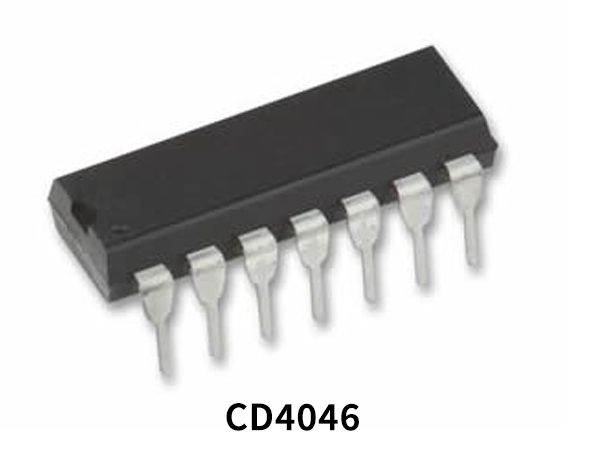
CD4046 Pinout
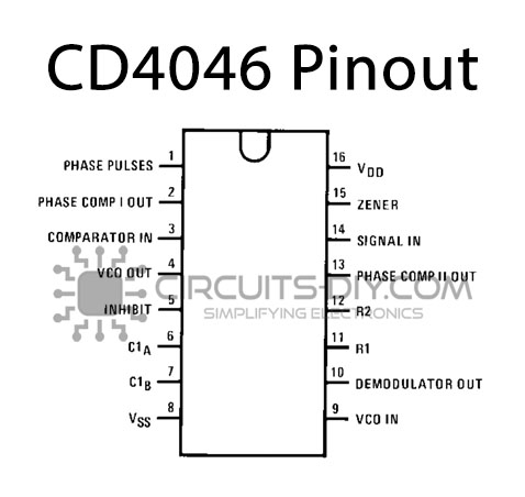
| Pin No | Pin Name | Description |
|---|---|---|
| 1 | Phase Pulse | Phase pulse applied to the IC |
| 2 | Phase- Comp I Out | output of Phase Comparator I |
| 3 | Comparator IN | Input at the Comparator |
| 4 | VCO OUT | Output Signal at VCO |
| 5 | INHIBIT | electronically turn on or off the output voltage |
| 6 | C1A | Capacitor 1 connected to VCO |
| 7 | C1B | Capacitor 2 connected to VCO |
| 8 | VSS | source supply |
| 9 | VCO IN | Input Signal at VCO |
| 10 | D- OUT | Extracting the original signal |
| 11 | R1 | Resistor 1 connected between VCO and Supply Voltage |
| 12 | R2 | Resistor 2 connected between VCO and Supply Voltage |
| 13 | Phase- Comp II OUT | Generated oscillated output at Phase II Comparator |
| 14 | Signal IN | Input Signal applied to the Phase Comparator I |
| 15 | Zener | Zener diode for voltage regulation |
| 16 | VDD | Drain supply |
Application
- FM demodulator and modulator
- Frequency synthesis and multiplication
- Frequency discrimination
- Data synchronization and conditioning
- Voltage-to-frequency conversion
- Tone decoding
- FSK modulation
- Motor speed control
CD4046 Datasheet
You can download the datasheet for CD4046 Micropower Phase-locked Loop IC from the link given below:
See Also: CD40193 8-bit Up/Down Binary Counter – Datasheet | CD4502 Strobed Hex Inverter/Buffer – Datasheet | CD4067 16-channel Analog Multiplexer/Demultiplexer Datasheet