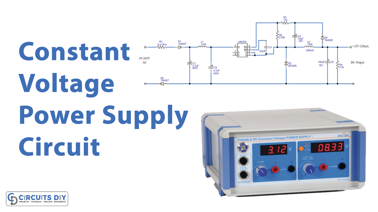
In this tutorial, we are going to make a “Constant Voltage Power Supply Circuit”.
Most electronic circuits are designed to operate at a constant voltage because they cannot operate properly if the voltage fluctuates in an unintended manner. A constant-voltage power supply is a power circuit that controls the output voltage to a constant level. It always supplies a constant voltage regardless of the load and is widely used in power supplies for electronic circuits. We should keep in mind that different voltage standards are followed by different countries when we design an electronic product.
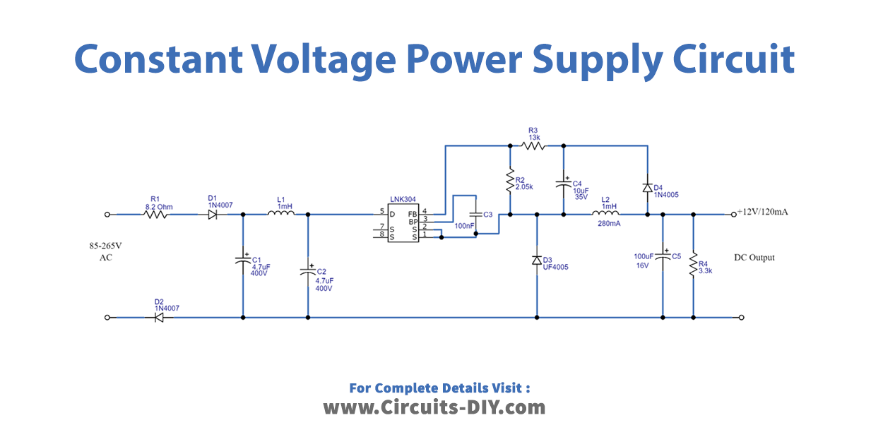
Here we design a universal input (85-265 VAC) and constant voltage power supply circuit (12 V, 120 mA) by using LinkSwitch-TN LNK304 from power integrations. The LNK304 is the lowest component count, energy-efficient Off-Line switcher IC suitable for AC to DC buck converter applications and also switch mode power supply, due to its Universal input voltage range (85 VAC to 265 VAC) we can design a transformer-less power supply circuit without any complications. This circuit is a typical application of LNK304.
Hardware Required
| S.no | Component | Value | Qty |
|---|---|---|---|
| 1. | Fusible Resistor | 8.2Ω, 2W | 1 |
| 2. | IC | LNK304 | 1 |
| 3. | Resistor | 2.05KΩ, 13KΩ, 3.3KΩ | 1,1,1 |
| 4. | Diode | 1N4007 | 2 |
| 5. | Capacitor | 4.7uF/400V, 100nF, 10uF/35V, 100uF/16V | 2,1,1,1 |
| 6. | Diode | UF4005 | 1 |
| 7. | Diode | 1N4005GP | 1 |
| 8. | Inductor | 1mH | 2 |
Circuit Diagram
IC LNK304

LinkSwitch-TN LNK304 IC is specifically designed to replace all linear and capacitor-fed (cap dropper) non-isolated power supplies in the under 360 mA output current range at equal system cost while offering much higher performance and energy efficiency. It has many notable features and helps to design low-cost minimum component buck converter circuits, at 66 kHz operation with accurate current limit allows low-cost off-the-shelf 1 mH inductor for up to 120 mA output current and has tight tolerances and negligible temperature variation. This IC has fully integrated auto-restart for short-circuit, and open loop fault protection, and a high breakdown voltage of 700 V providing excellent input surge withstand. For more details refer to the datasheet.
Working Explanation
In this power supply circuit design, we have used the DIP-8Bp package LNK304 IC. This IC combines a high-voltage power MOSFET switch with a power supply controller in one device. Unlike conventional PWM (pulse width modulator) controllers, it uses a simple ON/OFF control to regulate the output voltage. The IC’s controller consists of an oscillator, feedback (sense and logic) circuit, 5.8 V regulator, BYPASS pin Under-voltage circuit, over-temperature protection, frequency jittering, a current limit circuit, leading-edge blanking, and a 700 V power MOSFET. The LinkSwitch-TN also incorporates additional circuitry for auto-restart. Here AC input supply voltage is given to the Drain pin through an R1 fusible resistor and D1 diode (placed for rectification) and L1 inductor. C1, C2, and L1 elements altogether make a filter at the input stage.
Now with bypass and feedback circuit elements DC output supply (12V, 120mA) is derived from the source pin. For the power processing stage at output diode D3, D4, and a few other components are placed. Here the output voltage regulation is maintained by skipping switching cycles, when the output voltage rises, the current into the feedback (FB) pin will rise. If this happens then subsequent cycles will be skipped until the current reduces feedback current. This circuit takes a universal input voltage range (85 VAC to 265 VAC) and provides 12V, 120mA DC output. It involves operating high voltage that can give a lethal shock, and should be handled with extreme caution.
Applications
- Can be used in timers.
- Can be used for LED drivers and industrial controls.