This article discusses three significant motors and their interface with a driver module’s microcontroller. This tutorial will interface “L293D Motor Driver with Arduino UNO”.
A DC motor is an electric motor that runs on DC (direct current).DC motors are used in a wide range of electronic devices. You’ve probably used it in several projects because DC motors appear to be used in every other application, whether industrial or academic.
Stepper motors get their name because each electrical pulse causes the motor to move one step forward. Thus, a pulsed electrical current is converted into a precise one-step controlled by a stepper motor driver in the stepper motor. Stepper motors are used in a variety of industries. Stepper motors are utilized in textile machines, printing presses, medical imaging machines, CNC machines, and many other machines.
Servo motors are commonly found in different machines, and we have extensively used them in automation and mechanical applications. Furthermore, these motors have a significant impact on robots and, as a result, have advanced mechatronics applications.
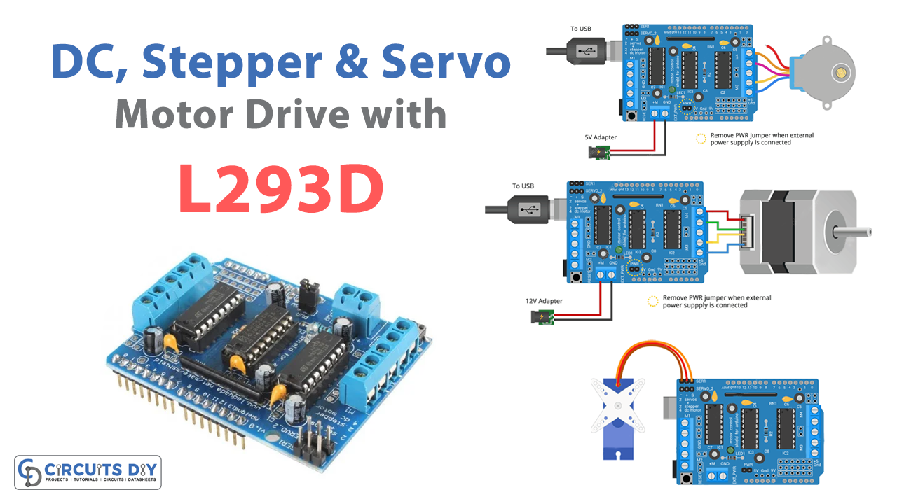
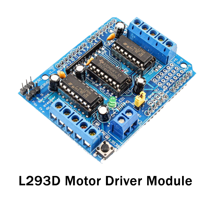
L293D Motor Driver Shield
The L293D is a simple motor driver module that allows us to control the speed and direction of DC, stepper, and servo motors. The L293D IC, a 16-pin IC with eight pins on each side for controlling the motor, is included in the module. A single L293D may therefore power up to two motors. Two H-bridge circuits make up the L293D. The H-bridge is the simplest primary circuit for altering polarity across a load.
Features
- Contains four half H-Bridges that can operate as two full H-Bridges
- Operate 2 motors with direction and speed control or 4 motors with speed control only
- Can supply 600mA current per channel continuous and 1.2A peak
- 4.5 to 36V motor voltage
- 5V compatible on logic pins
Pinout
| Pin Name | Description |
| IN1 | Motor A input pin. |
| IN2 | Motor A input pin. |
| IN3 | Motor B input pin. |
| IN4 | Motor B input pin |
| EN1 | Enables PWM signal for Motor A |
| EN2 | Enables PWM signal for Motor B |
| OUT1 | Output pin 1 of Motor A |
| OUT2 | Output pin 2 of motor A |
| OUT3 | The output pin of Motor B |
| OUT4 | Output pin 2 of motor B |
| 12V | 12V input from DC power Source |
| 5V | Supplies power for the switching logic circuitry inside L293D |
| GND | Ground pin |
Hardware Required
| S.no | Component | Value | Qty |
|---|---|---|---|
| 1. | Arduino UNO | – | 1 |
| 2. | USB Cable Type A to B | – | 1 |
| 3. | Jumper Wires | – | – |
| 4. | Motor Driver | L293D | 1 |
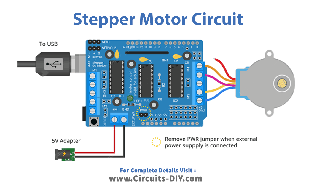
Circuit Diagram


Arduino Code
#include <AFMotor.h>

AF_DCMotor motor(4);

void setup()
{
	//Set initial speed of the motor & stop
	motor.setSpeed(200);
	motor.run(RELEASE);
}

void loop()
{
	uint8_t i;

	// Turn on motor
	motor.run(FORWARD);

	// Accelerate from zero to maximum speed
	for (i=0; i<255; i++)
	{
		motor.setSpeed(i);
		delay(10);
	}

	// Decelerate from maximum speed to zero
	for (i=255; i!=0; i--)
	{
		motor.setSpeed(i);
		delay(10);
	}

	// Now change motor direction
	motor.run(BACKWARD);

	// Accelerate from zero to maximum speed
	for (i=0; i<255; i++)
	{
		motor.setSpeed(i);
		delay(10);
	}

	// Decelerate from maximum speed to zero
	for (i=255; i!=0; i--)
	{
		motor.setSpeed(i);
		delay(10);
	}

	// Now turn off motor
	motor.run(RELEASE);
	delay(1000);
}
For NEMA 17 bipolar stepper
#include <AFMotor.h>

// Number of steps per output rotation
// Change this as per your motor's specification
const int stepsPerRevolution = 48;

// connect motor to port #2 (M3 and M4)
AF_Stepper motor(stepsPerRevolution, 2);

void setup() {
  Serial.begin(9600);
  Serial.println("Stepper test!");

  motor.setSpeed(10);  // 10 rpm
}

void loop() {
  Serial.println("Single coil steps");
  motor.step(100, FORWARD, SINGLE);
  motor.step(100, BACKWARD, SINGLE);

  Serial.println("Double coil steps");
  motor.step(100, FORWARD, DOUBLE);
  motor.step(100, BACKWARD, DOUBLE);

  Serial.println("Interleave coil steps");
  motor.step(100, FORWARD, INTERLEAVE);
  motor.step(100, BACKWARD, INTERLEAVE);

  Serial.println("Micrsostep steps");
  motor.step(100, FORWARD, MICROSTEP);
  motor.step(100, BACKWARD, MICROSTEP);
}
Driving Servo Motors with L293D Shield
#include <Servo.h>

Servo myservo;	// create servo object to control a servo
int pos = 0;	// variable to store the servo position

void setup()
{
	// attaches the servo on pin 10 to the servo object
	myservo.attach(10);
}

void loop()
{
	// sweeps from 0 degrees to 180 degrees
	for(pos = 0; pos <= 180; pos += 1)
	{
		myservo.write(pos);
		delay(15);
	}
	// sweeps from 180 degrees to 0 degrees
	for(pos = 180; pos>=0; pos-=1)
	{
		myservo.write(pos);
		delay(15);
	}
}
Working Explanation
To Control DC, Stepper & Servo with L293D Motor Driver Shield & Arduino, connect all the circuits according to the diagrams given. Upload the code in Arduino of respective circuits. Now observe the motors.
- DC motor, in the forward direction, would accelerate 0 to maximum, and then maximum to zero. Then in the backward direction, it goes from 0 to maximum, and then maximum to 0, and then it will turn OFF.
- The Stepper motor would take different steps according to the code.
- The Servo motor would move from 0 to 180 degrees and then 180 degrees to 0 DEGREES.
Code Explanation
Driving DC Motors with L293D Shield
- First, we have included the AFMotor.h library. declared the Arduino pin which is connected to the driver pins.
- In the void setup, we set the initial motor speed by using motor .setSpeed() function. And, to stop the motor, we have used motor.run(RELEASE)
- In the void loop, to run the motor we give the function motor.run(), and then by using for loop, we accelerate and decelerate the motor direction.
For NEMA 17 bipolar stepper
- First, we have included the AFMotor.h library. After that, we defined the variable stepsPerRevolution to store an integer number of steps required per revolution that our motor is rated at. Then we created the stepper library which uses the motor’s steps per rotation as a parameter, as well as the Arduino pin connections.
- In the void setup, we initialize the serial monitor. Then, we call the motor .setSpeed() function to set the speed and write the motor rpms in the bracket
- In the void loop, we have called the step() function which controls the motor at a certain speed and at a prescribed number of steps.
Driving Servo Motors with L2
- First, we have included the servo.h library. Then we created the object mysevo. Then we define the variable pos to store the servo position.
- In the void setup, to declare the Arduino pin to which the servo is connected, we use myservo.attach function.
- In the void loop, we made the program by giving for a loop. The function allows servo to first move from 0 to 180 degrees, and then 180 to 0 degrees.
Application and Uses
These three circuits are used to drive three motors, like DC, servo, and stepper motors. Thus these motors have many applications in different industries, including robotics, consumer electronics, mechatronics, automation, etc.