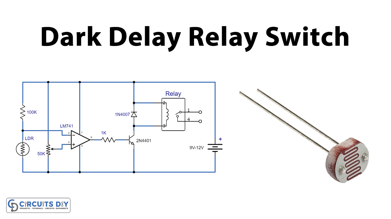
The dark sensor relay switch is an electrical circuit that is used to detect light. The device uses the LDR light-sensing property to turn the device on. It means when there is no light on the LDR board, the circuit will activate the relay switch.
The LDR (Light Dependent Resistor) has very high resistance in darkness as much as 10 Meg ohms which in bright light decreases to a few ohms. The circuit is designed around an operational amplifier IC LM741. The main purpose of this LM741 operational amplifier IC is to amplify signals from AC and DC and for math operations.
Hardware Components
The following components are required to make Dark Sensor Relay Switch Circuit
| S.no | Components | Value | Qty |
|---|---|---|---|
| 1. | Resistors | 1K, 100K | 1,1 |
| 2. | Potentiometer | 50K | 1 |
| 3. | Operational amplifier IC | LM741 | 1 |
| 4. | LDR | – | 1 |
| 5. | Transistor | 2N4401 | 1 |
| 6. | Diode | 1N4007 | 1 |
| 7. | DC Power supply | 9v-12v | 1 |
| 8. | Relay | – | 1 |
LM741 Pinout

For a detailed description of pinout, dimension features, and specifications download the datasheet of LM741
Dark Sensor Relay Switch Circuit
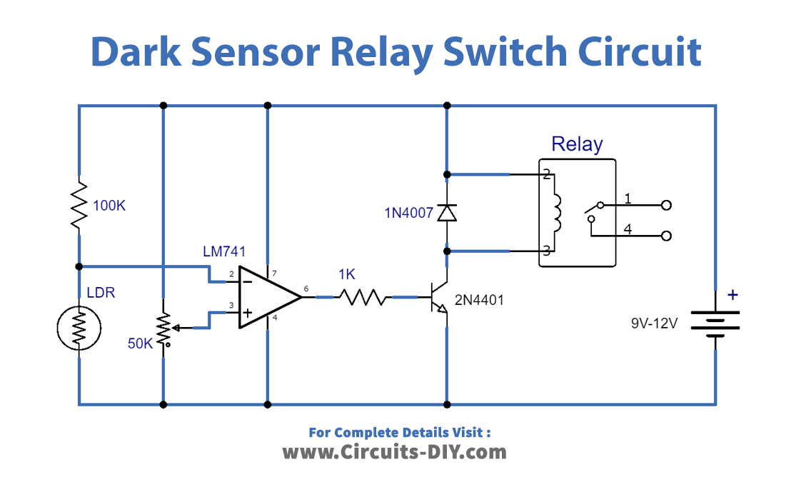
Working Explanation
The circuit can be worked with between 9 volts to 12 volts DC. The output of the operational amplifier IC LM741 used in the circuit is 25mA which is not enough to directly drive the relay so it is generated from a 2N4401 transistor. A variable resistor can be used to build a dark sensor relay circuit. The circuit sensitivity is modified by that 150K variable resistor. LDR is used in the circuit to turn on the device.
Applications and Uses
A dark sensor relay switch circuit is immensely useful and flexible, from automated illumination to surveillance devices, in a broad variety of renewable energy projects.