Introduction
Headphones. Who are not aware of them. Like other electronic gadgets, headphones have also become a prominent device for our everyday use. However, no one likes the bad sound quality with greater noise. Therefore, the makers try their best to use the best quality amplifiers in their headphones. So, we decided why not in this tutorial; we make the headphone amplifier circuit of low noise. So, in this tutorial, we are going to make a “HiFi Headphone amplifier circuit using TL072 low noise”.
In the making of the circuit, we are using TL072 IC. So before moving forward, let us discuss some of its features. With features like minimal offset (1 mV, typically), high slew rate (20 V/s), and common-mode input to the positive supply, TL072 devices offer exceptional value for applications that must be cost-effective.
TL072 Features
- High slew rate: 20 V/µs (TL07xH, typ)
- Low offset voltage: 1 mV (TL07xH, typ)
- Low offset voltage drift: 2 µV/°C
- Low power consumption: 940 µA/ch (TL07xH, typ)
- Wide common-mode and differential voltage ranges
- Low input bias and offset currents
- Low noise: Vn = 18 nV/√Hz (typ) at f = 1 kHz
- Output short-circuit protection
- Low total harmonic distortion: 0.003% (typ)
- Wide supply voltage: ±2.25 V to ±20 V, 4.5 V to 40
Hardware Required
| S.no | Component | Value | Qty |
|---|---|---|---|
| 1. | Transistor | BC142 & BC143 | 2, 2 |
| 2. | Variable Resistor | 47K | 2 |
| 3. | Resistor(different Values) | – | 12 |
| 4. | Capacitor | 10uF,100uF | 2, 2 |
| 5. | IC | TL072 | 2 |
| 6. | Headphone | – | 1 |
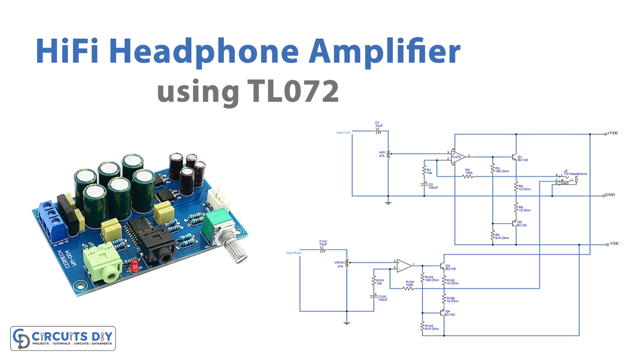
Circuit Diagram

Working Explanation
This HiFi Headphone amplifier circuit using TL072 low noise includes two different channels, left and right. Since both channels are similar, thus, we are explaining one channel.
Firstly, J1 and C1 are from where the audio signal enters the circuit. A coupling capacitor called C1 is used to block DC voltage. The signal volume is then adjusted by VR1. This results in an input impedance of around 47K, which is equal to VR1. For, the low noise signal amplifier we are using TL072 op-amp, configured to become a non-inverting circuit.
the output comes from pin 1 of IC1. As the bias current to the bases of transistors Q1, and Q2, both R3 and R4 resistors are configured in the class A mode. The fundamental components of this class A design are the two resistors R5 and R6. They improved the stability of the output portion by setting the feedback signal there.
The inverting pin of the IC will receive the feedback signal from the output after turning through resistor R2. R1 and R2 decide how much gain IC has.
Application Uses
- The sound is great. In situations where less distortion is needed, this can be employed.
- Because this headphone amplifier has a power output of around 120 mW, it would be good for headphones with 8 to 32 ohms.