Pull-up and Pull-down resistors are very common when using microcontrollers or any other digital logic device. The input and output pins of these devices should be correctly set to the either HIGH or LOW state for the digital circuit to function correctly. These logic states are represented by two different voltage levels with any voltage below one level is regarded as logic “0” and any voltage above another level is regarded as logic “1”. If the input to a digital logic gate is not within the range by which it can be sensed as either logic 0 or a logic 1, then the circuit may false trigger and the desired result cannot be obtained.
In this tutorial, we will show you how a Pull-up and Pull-down resistor works. To simulate the circuit we will be using Proteus software.
Hardware Components
Following are the necessary hardware items required for Pull-up and Pull-down Circuit:
Connection
- Open the Proteus Software
- Pick the components (mentioned above) from the library.
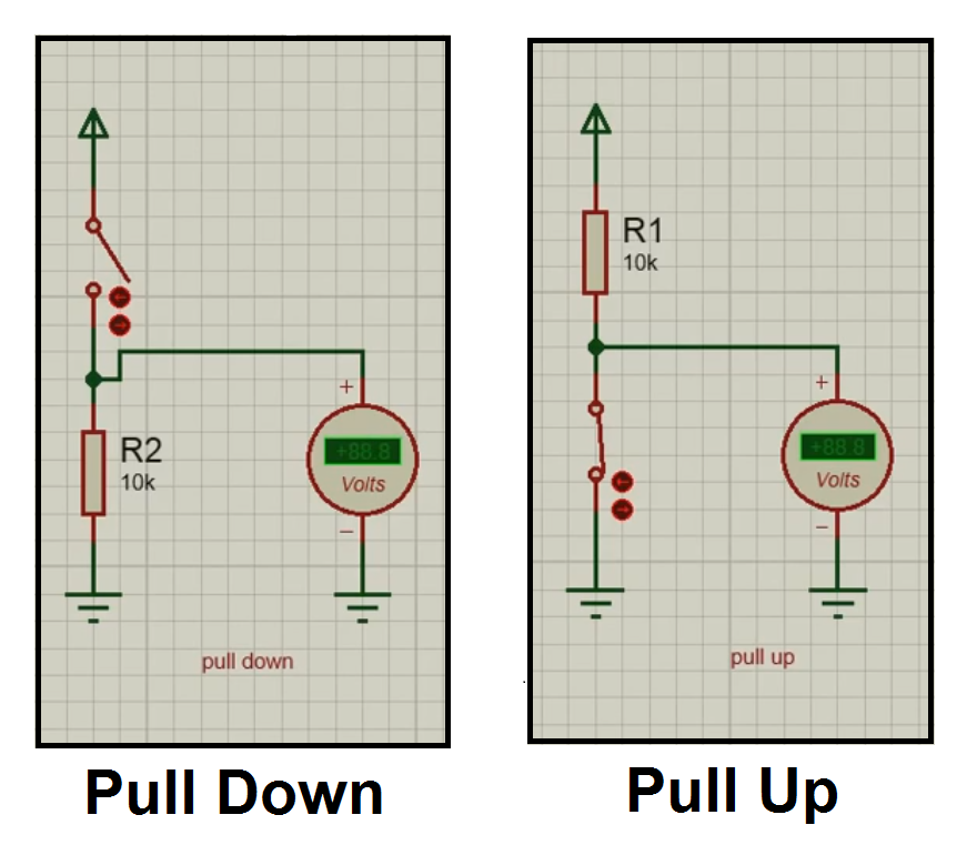
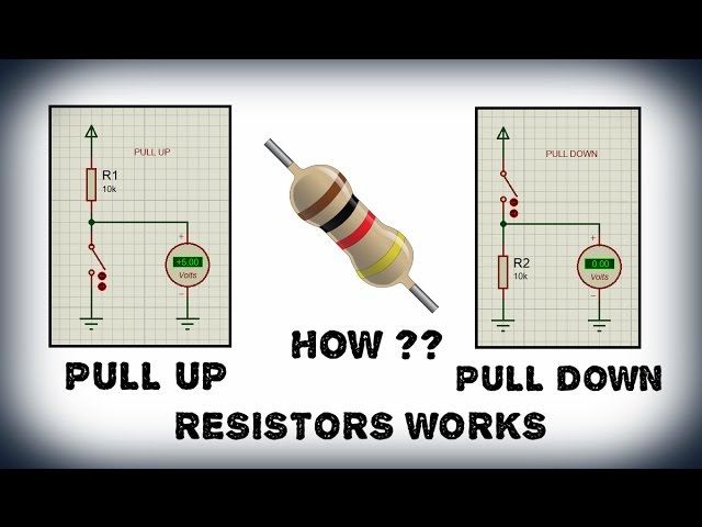
- For the circuit of Pull-up Resistor, Connect the 10K resistor directly to +5V and then connect the switch and GND.
- Connect the voltmeter in parallel with the switch.
- For the circuit of Pull-down Resistor, Connect the switch to the +5V and then connect the 10K resistor and GND.
- Connect the voltmeter in parallel with the resistor.
Working Explanation
Pull-up resistors are simply fixed value resistors, that are connected between the particular pin and the voltage supply. The value at the Pin will always be High when the switch is in Open state. When the switch is closed, the Pin will be connected directly to the ground and the output to the Pin will be Low. To show the output of the circuit, we have connected a voltmeter in parallel to the switch.
Like pull-up resistors, Pull-down resistors also work in the same way but they pull the pin to a low value. They are connected between a particular pin on a microcontroller and the ground terminal. When the switch is open, the Pin will be in Low state and once the switch is closed it will change to High state.
Application
- This circuit is widely used for interfacing devices to microcontrollers
- Pull-up and pull-down resistors are also used in I2C control bus.
Circuit Diagram