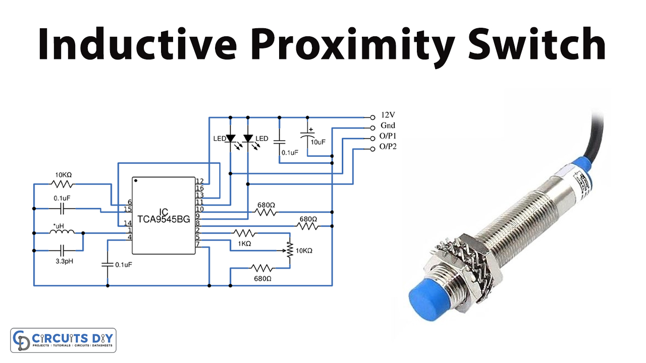
In this tutorial, we are going to make an “Inductive Proximity Switch Circuit”.
An inductive Proximity Switch is a device that causes a switching action without physical contact. As Proximity can be defined as Closeness, inductive proximity switches respond to targets that come within the active range of their generated sensing fields and have magnetic characteristics like metal objects. These switches are completely self-contained, and house a field generator, amplifier, and other necessary circuitry to accomplish electronic switching.
In this project, we designed a simple inductive proximity switch circuit by using IC TCA505BG from Siemens. Besides its basic functions (oscillator, demodulator, and threshold switch), the bipolar monolithic IC TCA505BG includes useful extra functions that enable high-grade, inductive proximity switches to be designed for an attractive price/performance ratio and with space savings. This IC is a proximity switch with short circuit production. It has a wide supply voltage range from 4V to 40V and consumes a low current of less than 0. 8mA. It has short circuit and overload protection of output stages and external components.
Hardware Components
The following components are required to make an Inductive Proximity Switch Circuit
| S.no | Component | Value | Qty |
|---|---|---|---|
| 1. | IC | TCA505BG | 1 |
| 2. | Capacitor | 0.1µF, 10µF | 3, 1 |
| 3. | Capacitor | 3.3pH | 1 |
| 4. | Resistor | 680Ω,10kΩ,1KΩ | 3, 1, 1 |
| 5. | Potentiometer | 10KΩ | 1 |
| 6. | LED | – | 2 |
| 7. | Connecting Wires | – | 1 |
| 8. | Power supply | 12V | 1 |
TCA505BG Pinout
For a detailed description of pinout, dimension features, and specifications download the datasheet of TCA505BG
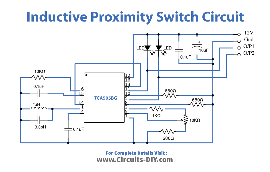
Inductive Proximity Switch Circuit
Working Explanation
The main part of this proximity Switch circuit is Sensing Inductor L1, Use Inductor wire-wound range from 490µH to 720µH as a Sensing Inductor L1, test with the prototype before fixing the L1 Value. This Circuit is designed to operate with a 12V DC supply. Now the resonant circuit of the LC oscillator is implemented with an open half-pot ferrite and a capacitor in parallel (pin LC, depending on Inductor L1 Value and tank circuit L1, C1 inductive proximity sensing range will vary on an average 3mm – 15mm). If a metallic target is moved closer to the open side of the half-pot ferrite, energy is drawn from the resonant circuit and the amplitude of the oscillation is reduced accordingly. This change in amplitude is transmitted to a threshold switch by means of a demodulator and triggers the outputs.
In this circuit D1 LED indicates the detection of metal or proximity. D2 LED indicates no detection of metal or proximity. Normally D2 LED is on, when the coil detects the metal object D2-LED goes off and D1 LED turns on, so O/P-2 provides the low output and O/P-1 provides High output when the metal object is detected. RV1 potentiometer helps to adjust the sensor sensitivity distance.
Applications
This circuit can be used for the detection of metal objects or as a positioning sensor.