Introduction
To check the voltages in the circuits, we all use the voltmeter. By definition, volumeter. is a device that monitors the difference in voltage or potential between two points in an electronic circuit. However, there are different types of voltmeters. One of them is the LEd voltmeter which is the main concern of this article. Because, in this tutorial, we are going to make the “LED Voltmeter circuit”. LED voltmeter includes different LEDs to indicate different voltages.
This voltmeter is easier to make for beginners as it requires very few electronics components including opamp IC 741. Here are some of its features

Hardware Components
The following components are required to make LED Voltmeter Circuit
LM741 Pinout

For a detailed description of pinout, dimension features, and specifications download the datasheet of LM741
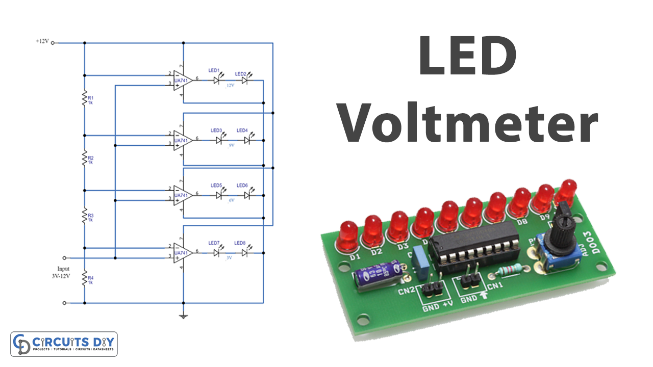
LED Voltmeter Circuit
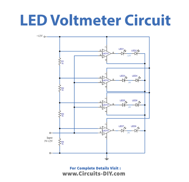
Working Explanation
The LED Voltmeter circuit has the voltage divider resistor network which receives the inverting input from the operational amplifier. Each resistor from R1 to R4 drops a certain voltage from the input, which is then delivered to the comparator operational amplifiers.
There are several LEDs in the circuit; LED1 and LED2 indicate a voltage level of up to 12 Volt, while LED7 and LED8 indicate a voltage level of less than 3 Volt input. Each op-amp is supplied by a single 12-volt power supply. Thus, 12V is shown by IC1 having LED1 and LED 2; 9V is shown by IC2 having LED 3 and LED4; 6V is shown by IC3 having LED5 and LED 6; 3V is shown by IC4 having LED7 and LED 8
Application and Uses
- It can be used in any circuit that needs to check the voltage from 3V to 12V.