In this tutorial, we are going to make a “Portable Power Supply Unit”. A portable power supply is a device, that allows you to stay plugged in. It can fully charge your battery-powered devices, during outdoor adventures. Because every electronic circuit needs a power source to operate, it is necessary to possess a ready-to-use power source for prototyping and testing electronics. Today, they usually have inbuilt inverters, that make it easy for them to charge AC devices.
And they can be recharged, using the car’s battery or solar. Whether it’s a television, heater, premium tent fan, smartphone, or microwave. You don’t have to sacrifice your comfort, just because there is no electricity. Here proposed of the following design is a reliable and easy-to-carry portable power supply unit. It is capable of providing DC output voltage, between 5V to 26V. This can be charged through AC input, and also USB power from gadget chargers or other power sources.
Hardware Required
| S.no | Components | Value | Qty |
|---|---|---|---|
| 1. | IC | LM7805 | 1 |
| 2. | Zener Diode | 5.1V/1W | 1 |
| 3. | Diode | 1N4007 | 5 |
| 4. | Resistor | 470KΩ,100Ω/2W,100Ω/1W,10Ω/1W | 1,1,1,1 |
| 5. | Capacitor | 225kf,1000uf/25V,0.1uf | 1,1,1 |
| 6. | TP4056 Mini USB – Lithium Battery Charger Module | – | 1 |
| 7. | Li-Ion Battery | – | 1 |
| 8. | DPDT Slide Switch | – | 1 |
| 9. | DC-DC Boost Converter Module | MT3608 | 1 |
| 10. | Connecting Wires | – | – |
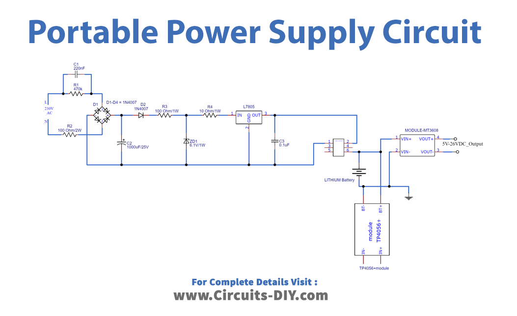
Portable Power Supply Unit Design
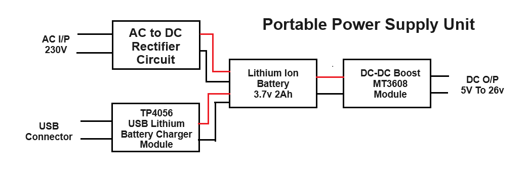
According to the block diagram, this design contains four blocks in a compact space. In one block we have used the Lithium Ion battery 3.7V – 2000 mAh, as a rechargeable power source. Here rectifier circuit converts 230V AC input to 5V DC output. And USB to Lithium battery charger module gives DC supply to the battery, both inputs are controlled by the DPDT slide switch. And the DC-DC boost converter module gives 5V to 26V DC, from a Li-Ion battery.
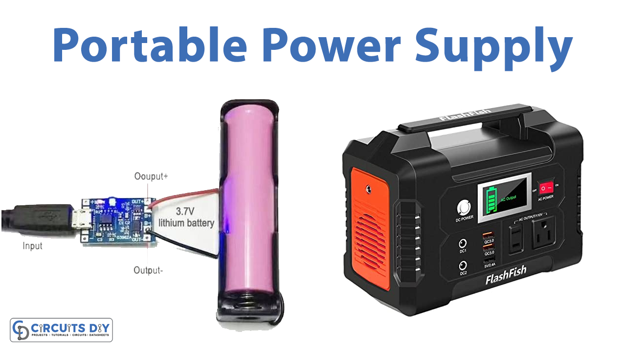
Portable Power Supply
Working Explanation
As we can see in the circuit, the rectifier circuit is designed using discrete components. Which is used to convert 230V AC to 5V DC. Here the output from the rectifier is connected to the A1 and A2 pins of the Slide switch. Now TP4056 mini USB – Lithium battery charger module takes input from the mobile charger or USB power sources. And gives a constant current charging supply to the Li-Ion battery. Output from this module is connected to the B1 and B2 terminals of the slide switch. Terminals C1 and C2 are connected to the Lithium Ion battery (always mind the polarity +Ve, -Ve). Here MT3608 DC-DC Boost module is directly connected to the Li-Ion battery terminals, and you can add an ON/OFF switch to control the output. This MT3608 module gives a step-up DC voltage of up to 26V, and the output voltage can be varied by the trimpot. We can choose the input power source to charge the battery by using the DPDT slide switch. This design includes a high-voltage input, so handles with extreme care. Also, be more cautious to handle Lithium Ion batteries and do not short circuit any part.
Application
This project is ideal for emergencies and can be used on construction sites. Such as at gatherings, or more generally for non-grid-connected locations (outdoor fairs, campsites, off-grid sites, etc..).