To know about frequency modulation we are here with another exciting tutorial on a Small FM bug Transmitter Circuit that allows you to transmit the signal within 1 or 2 Km of range. Hence, the circuit works effectively in that range. Basically, frequency modulation transfers the data or information by varying the frequency of carrier waves. We can create the circuit in different ways but for your understanding, we are creating the simplest circuit using one transistor. Thus, the circuit also requires some other external components which are easily available.
Hardware Required
| S.no | Component | Value | Qty |
|---|---|---|---|
| 1. | PNP Transistor | BC557 | 2 |
| 2. | Microphone Condenser | – | 1 |
| 3. | LED | – | 1 |
| 4. | Inductor | 0.5 mm | 1 |
| 5. | Single-stranded wire | Antenna | 1 |
| 6. | Ceramic Capacitor | 1nF, 33pF, 47pF | 1, 1, 1 |
| 7. | Resistor | 4.7KΩ, 330Ω, 1KΩ | 1, 1, 1 |
| 8. | Battery | 9v | 1 |
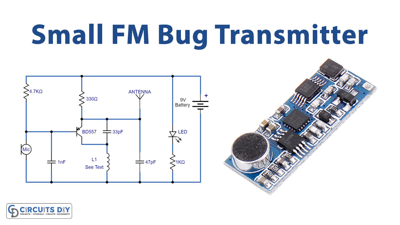
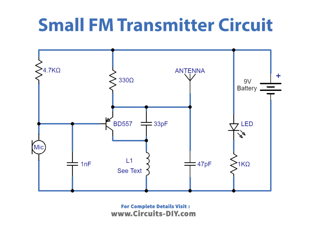
Circuit Diagram
Working Explanation
In this Small FM bug Transmitter, we are using the condenser microphone that provides the audio signal. When the circuit gets an audio signal from the microphone, it converts the signal into electrical energy, and then that electrical signal goes through the base of the transistor. This will increases the amplitude of the signal. Now to generate the carrier waves, we have created the tank circuit using a capacitor and coil. We have made the coil L1 from 0.5 mm coated copper wire by giving six to seven turns in the diameter of a normal pencil. We have connected an antenna to send those carrier waves. The antenna is simply a piece of wire. LED in the circuit is there to indicate the presence of supply.
Application and Uses
- Portable audio devices.
- In car radios, etc