Introduction
An edge detection robot is a fascinating and practical application of robotics that uses infrared (IR) sensor modules to navigate along an edge or line. Using an Arduino UNO microcontroller board and DC motors, the robot can be programmed to move along a specific path, such as the edge of a table or a line on the floor. IR sensor modules detect the presence of the surface, and the robot’s movements can be controlled based on this feedback.
The use of Arduino UNO and DC motors makes this an accessible and popular DIY project for robotics enthusiasts, students, and hobbyists alike. Edge detection robots have a wide range of applications, from simple line-following robots to more complex applications in industrial automation, agriculture, and logistics.
Hardware Components
You will require the following hardware for the Edge detection robot.
| Components | Value | Qty |
|---|---|---|
| Arduino UNO | – | 1 |
| IR Sensor | – | 1 |
| BO Motor | – | 1 |
| Chassis | – | 1 |
| Breadboard | – | 1 |
| Jumper Wires | – | 1 |
Code Explanation
Step 1: Define pins for sensor inputs and motor outputs
void setup() {
  pinMode(7, INPUT);  //left sensor output to Arduino input
  pinMode(6, INPUT);  //right sensor output to Arduino input
  pinMode(0, OUTPUT); //output from Arduino to motor driver, right motor
  pinMode(1, OUTPUT); //output from Arduino to motor driver, right motor
  pinMode(2, OUTPUT); //output from Arduino to motor driver, left motor
  pinMode(3, OUTPUT); //output from Arduino to motor driver, left motor
}
In this step, the Arduino pins are defined for the sensor inputs and motor outputs. Pins 7 and 6 are set as inputs to receive signals from the left and right sensors, respectively. Pins 0-3 are set as outputs to control the two motors that drive the robot’s wheels.
Step 2: Read sensor inputs and control motors based on the input values
void loop() {
  //Read sensor inputs
  int l1 = digitalRead(7); //left sensor input
  int r1 = digitalRead(6); //right sensor input

  //Control motors based on sensor inputs
  if ((l1 == HIGH) && (r1 == HIGH)) { //if both sensors detect the line
    //Stay still
    digitalWrite(0, LOW);
    digitalWrite(1, LOW);
    digitalWrite(2, LOW);
    digitalWrite(3, LOW);
  }
  else if ((l1 == LOW) && (r1 == HIGH)) { //if only the right sensor detects the line
    //Turn right
    digitalWrite(0, HIGH);
    digitalWrite(1, LOW);
    digitalWrite(2, LOW);
    digitalWrite(3, HIGH);
  }
  else if ((l1 == HIGH) && (r1 == LOW)) { //if only the left sensor detects the line
    //Turn left
    digitalWrite(0, LOW);
    digitalWrite(1, HIGH);
    digitalWrite(2, HIGH);
    digitalWrite(3, LOW);
  }
  else if ((l1 == LOW) && (r1 == LOW)) { //if neither sensor detects the line
    //Stop the robot
    digitalWrite(0, LOW);
    digitalWrite(1, HIGH);
    digitalWrite(2, LOW);
    digitalWrite(3, HIGH);
  }
}
In this step, the sensor inputs are read into variables l1 and r1 using the digitalRead() function. Based on the sensor readings, the robot is commanded to move in different directions.
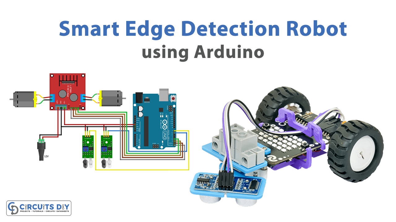
Schematic
Make connections according to the circuit diagram given below.

Installing Arduino IDE
First, you need to install Arduino IDE Software from its official website Arduino. Here is a simple step-by-step guide on “How to install Arduino IDE“.
Code
Now copy the following code and upload it to Arduino IDE Software.
void setup() {
  //left sensor output to Arduino input
  pinMode(7, INPUT);

  //Right Sensor output to Arduino input
  pinMode(6, INPUT);

  //output from Arduino to motor driver, right motor
  pinMode(0, OUTPUT);
  pinMode(1, OUTPUT);

  //output from Arduino to motor driver, left motor
  pinMode(2, OUTPUT);
  pinMode(3, OUTPUT);
}

void loop() {
  //left sensor input
  int l1 = digitalRead(7);

  //Right Sensor Input
  int r1 = digitalRead(6);

  if((l1 == HIGH) && (r1 == HIGH)) { //if both sensors detect the line
    //Stay still
    digitalWrite(0, LOW);
    digitalWrite(1, LOW);
    digitalWrite(2, LOW);
    digitalWrite(3, LOW);
  }
  else if((l1 == LOW) && (r1 == HIGH)) { //if only the right sensor detects the line
    //Turn right
    digitalWrite(0, HIGH);
    digitalWrite(1, LOW);
    digitalWrite(2, LOW);
    digitalWrite(3, HIGH);
  }
  else if((l1 == HIGH) && (r1 == LOW)) { //if only the left sensor detects the line
    //Turn left
    digitalWrite(0, LOW);
    digitalWrite(1, HIGH);
    digitalWrite(2, HIGH);
    digitalWrite(3, LOW);
  }
  else if((l1 == LOW) && (r1 == LOW)) { //if neither sensor detects the line
    //Stop the robot
    digitalWrite(0, LOW);
    digitalWrite(1, HIGH);
    digitalWrite(2, LOW);
    digitalWrite(3, HIGH);
  }
}
Working Explanation
In the setup() function, pins 7 and 6 are set as inputs to receive signals from the left and right sensors, respectively. Pins 0-3 are set as outputs to control the two motors that drive the robot’s wheels. In the loop() function, the signals from the two sensors are read into variables l1 and r1 using the digitalRead() function. Then, based on the sensor readings, the robot is commanded to move in different directions.
If both sensors detect the line (l1 and r1 are HIGH), the robot stays still. If only the right sensor detects the line (l1 is LOW and r1 is HIGH), the robot turns right by setting the right motor to go forward and the left motor to go backward. Similarly, if only the left sensor detects the line (l1 is HIGH and r1 is LOW), the robot turns left by setting the left motor to go forward and the right motor to go backward. If neither sensor detects the line (l1 and r1 are both LOW), the robot stops by setting both motors to go backward.
Applications
- Industrial automation
- Agriculture
- Logistics
- Surveillance
- Education and research